Angled axis machine vision system and method

a machine vision and axis technology, applied in the field of machine vision systems, can solve the problems of low accuracy of the estimate of the three-dimensional position of the feature, the most problematic feature, and the match is completely ambiguous and unusable, so as to facilitate the vision of people, design and manufacture, and minimize processing and error in distance calculations

Inactive Publication Date: 2006-01-19
VISION ROBOTICS
View PDF12 Cites 30 Cited by
  • Summary
  • Abstract
  • Description
  • Claims
  • Application Information

AI Technical Summary

Benefits of technology

[0018] Standard CMOS and CCD cameras have a 4:3 aspect ratio (640:480). Rotating the cameras 36.9 degrees aligns the diagonal of the camera images with real worlds' horizon. Thus the cameras give the widest horizontal viewing angle with respect to the ground. “Substantially 37 degrees” means any mounting angled to take advantage of the diagonal of a 4:3 aspect ratio camera that is in keeping with the spirit of the invention, namely between purely horizontal and purely vertical, or 0 and 90 degrees but closer to 37 degrees than 45 or 29 degrees.
[0019] In another embodiment, the cameras are parallel to the ground and rotated 45 degrees. A 45-degree orientation optimally rotates the cameras and, thus, the line between the camera centers is not parallel to either the horizontal and vertical lines in the environment. Additionally, after horizontal and vertical, 45-degree angles are the most common and are easy for people to envision, design and manufacture. “Substantially 45 degrees ” means any mounting angled to take advantage of the diagonal of a 1:1 aspect ratio camera that is in keeping with the spirit of the invention, namely between purely horizontal and purely vertical, or 0 and 90 degrees but closer to 45 degrees than 37 or 29 degrees.
[0020] In another embodiment, the cameras are parallel to the ground and rotated 29.4 degrees. A 29.4-degree orientation optimally rotates cameras with 16:9 asp...

Problems solved by technology

Any feature in one image that can be matched with several features in the other image is problematic and either must be ignored or leads to low accuracy for the estimate of the feature's three-dimensional position.
The type of feature that is the most problematic is any line that is parallel to the axis defined in the direction between the camera centers.
This is because every portion of the line in the first image matches every portion of the line in the second image equally well so the match is completely ambiguous and unusable.
Lines that are not quite parallel to the line between the camera centers are also problematic.
While there is a theoretical best match, slight problems such as lighting discontinuities render these lines that are close to pa...

Method used


Image

  • Angled axis machine vision system and method
  • Angled axis machine vision system and method
  • Angled axis machine vision system and method

Examples


Embodiment Construction

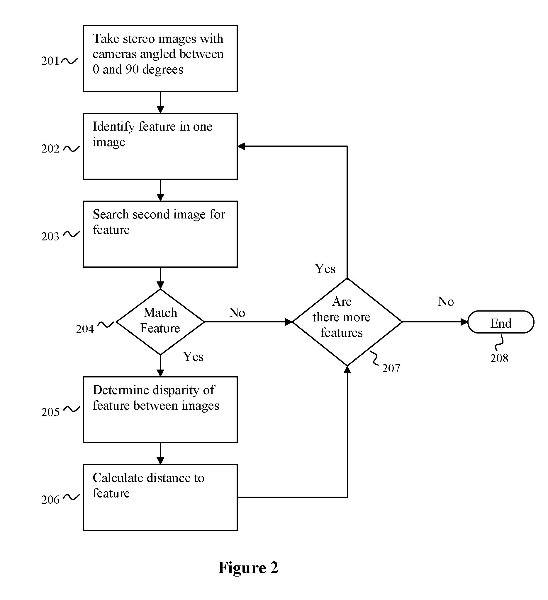
[0030] Embodiments of the invention comprise an angled axis machine vision system having a camera system angled with respect to an axis of the coordinate system of the environment. This configuration has all of the advantages of the horizontal alignment while eliminating the inherent problem of utilizing horizontal and vertical lines in an environment for distance calculations when the horizontal and vertical lines are parallel or close to parallel to an axis lying between camera centers of the camera system. With the camera centers angled about the roll axis, horizontal and vertical lines in the environment appear as angled lines in images taken from the cameras enabling more accurate distance calculations. With the camera centers angled downward about the pitch axis objects that are near are more readily observed. With angled axis rotation it is still possible for lines in the environment to be parallel to the axis defined between the camera centers, but these instances are rarer ...


PUM


Abstract

Embodiments of the invention comprise an angled axis machine vision system having a camera system angled with respect to an axis of the coordinate system of the environment. This configuration has all of the advantages of the horizontal alignment while eliminating the inherent problem of utilizing horizontal and vertical lines in an environment for distance calculations when the horizontal and vertical lines are parallel or close to parallel to an axis lying between camera centers of the camera system. With the camera centers angled about the roll axis, horizontal and vertical lines in the environment appear as angled lines in images taken from the cameras enabling more accurate distance calculations. With the camera centers angled downward about the pitch axis objects that are near are more readily observed. With angled axis rotation it is still possible for lines in the environment to be parallel to the axis defined between the camera centers, but these instances are rarer than horizontal or vertical lines in real world environments. Embodiments of the invention may comprise a camera mount that is rotatably mounted to a support wherein two sets of pictures from each of the cameras may either be utilized. In one embodiment the two sets are compared for the number of lines which are parallel to the axis of the camera centers and the set of pictures with the least lines parallel is used for distance calculations. In another embodiment, the two sets are utilized to correlate the distances derived from each set of pictures.

Description

BACKGROUND OF INVENTION [0001] 1. Field of the Invention [0002] Embodiments of the invention described herein pertain to the field of machine vision systems. More particularly, but not by way of limitation, these embodiments yield improved calculation of distance in environments comprising substantially horizontal and substantially vertical features through use of stereo digital cameras that are rotated in at least one axis comprising at least the roll axis. [0003] 2. Description of the Related Art [0004] Machine vision systems allow computers to view the physical world. A machine vision system comprises at least one camera coupled with a computer. A computer is used to interpret an image taken from a camera thereby enabling a machine vision system to perform various tasks. Tasks performed by machine vision systems are diverse and include distance estimation that is used in applications involving robot navigation. The use of two cameras in order to calculate a distance to an object ...

Claims


Application Information

Patent Timeline
IPC IPC(8): H04N13/00H04N15/00H04N13/239
CPCH04N13/0239G06T2207/30252G06T7/002H04N2013/0081G06T7/85H04N13/239
Inventor KOSELKA, HARVEYWALLACH, BRET
Owner VISION ROBOTICS
Why Eureka
Try Eureka