

Microscope imaging system and method for emulating a high aperture imaging system, particularly for mask inspection
- Summary
- Abstract
- Description
- Claims
- Application Information
AI Technical Summary
Benefits of technology
Problems solved by technology
Method used
Image

Examples
Embodiment Construction
Imaging System for the Simulation of High-Aperture Scanner Systems
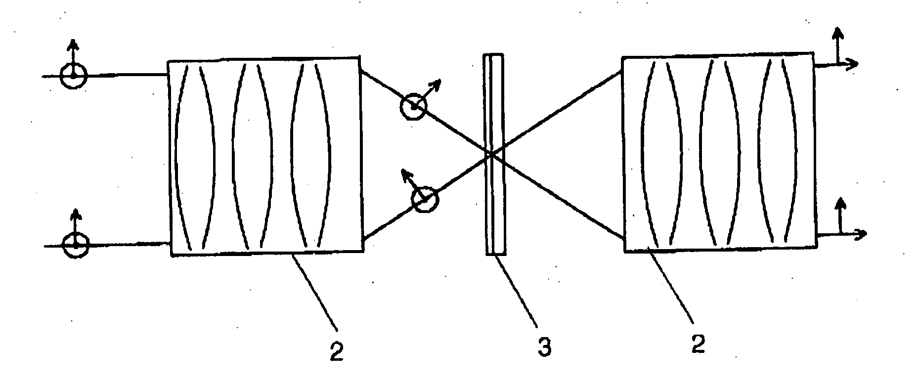
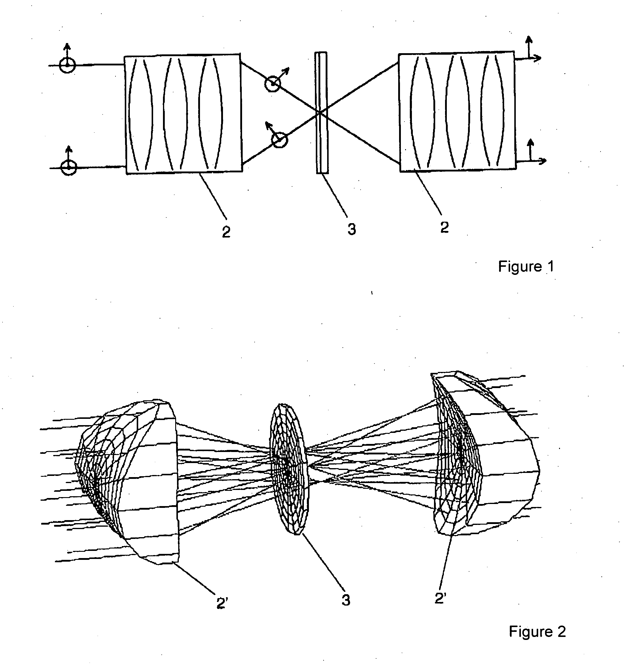
[0028] The microscope imaging system, according to the invention, for the emulation of high-aperture scanner systems, particularly for mask inspection, comprises illumination optics and imaging optics, a detector and an evaluating unit. Polarizing optical elements for generating different polarization states of the illumination beam are selectively arranged in the illumination beam path and / or in the imaging beam path for selecting different polarization components of the imaging beam. An optical element with a polarization-dependent intensity attenuation function can be introduced into the imaging beam path. Images of the mask and / or sample are received by the detector for differently polarized beam components. The images for differently polarized beam components are subsequently combined by an evaluating unit to form a total image. This is carried out, for example, by summing their intensity distributions.
Polari...
PUM
 Abstract
Description
Claims
Application Information