Magnetic sensor for encoder

a technology of magnetic sensor and encoder, which is applied in the direction of nanomagnetism, data recording, instruments, etc., can solve the problems of difficult to detect position with a high degree of precision, the proposed magnetic sensor cannot achieve such sensitivity, and the difficulty of many placements on the same plan

Inactive Publication Date: 2006-01-19
TDK CORPARATION
View PDF6 Cites 23 Cited by
  • Summary
  • Abstract
  • Description
  • Claims
  • Application Information

AI Technical Summary

Benefits of technology

[0010] It is therefore an object of the present invention to provide a magnetic sensor for an encoder, whereby precise detection in position and high reliability in the detection can be expected.
[0012] Because the magnetic sensor has the sliding surface kept contact with the surface of the magnetic medium and also each MR element has linear sections or magnetic sensitive portion extending linearly, it is possible to increase sensitivity and output of each MR element. Thus, when used for a magnetic sensor of an encoder, extremely precise detection in position can be obtained to greatly improve reliability in the detection.
[0016] It is preferred that the magnetic sensor further includes electrode terminals formed on a surface of the magnetic sensor, which is different from a surface of the sensor faced to the magnetic medium, that is the sliding surface, and electrically connected to the MR elements, respectively. Because the electrode terminals are formed on the surface different from the sliding surface, the magnetic sensor can be extremely downsized and can be fabricated in low cost.

Problems solved by technology

However, it had become very difficult to arrange on the same plane many of MR elements each having a certain pattern width in order to satisfy a high resolution that is required for the encoder.
Thus, although it is necessary to have extremely high sensitivity, the proposed magnetic sensor cannot attain such sensitivity because of non-contact structure and using of normal anisotropic MR element structure.
Therefore, when the magnetic sensor disclose in Japanese patent publication No. 2002-206950A is used for a magnetic encoder, it is difficult to detect position with a high degree of precision.

Method used


Image

  • Magnetic sensor for encoder
  • Magnetic sensor for encoder
  • Magnetic sensor for encoder

Examples


Embodiment Construction

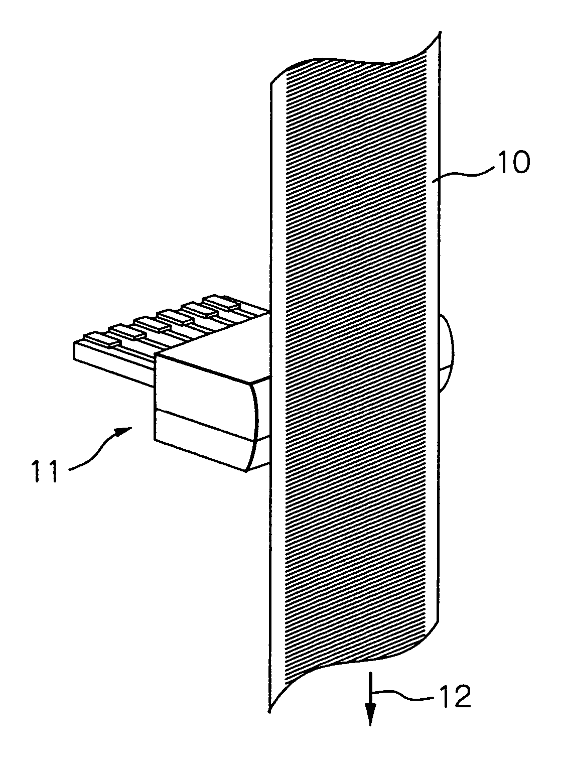
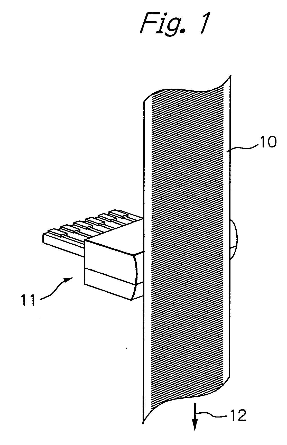
[0034]FIG. 1 schematically illustrates a configuration of a magnetic encoder as a preferred embodiment according to the present invention.

[0035] In the figure, reference numeral 10 denotes a magnetic medium to which a magnetic pattern with a predetermined magnetization pitch λ is recorded, and 11 denotes a magnetic sensor assembly with a sliding surface faced to and kept in contact with the magnetic medium 10, respectively.

[0036] In this embodiment, the magnetic medium 10 is fixed to a surface of an object (not shown) of which position and movement direction are to be detected. During operation, the magnetic sensor assembly 11 is held at rest with keeping in contact with the surface of the magnetic medium 10 like as a magnetic head of a magnetic tape drive apparatus or a flexible disk drive apparatus. The magnetic medium 10 relatively moves with respect to the magnetic sensor assembly 11 in a direction and / or the opposite direction of an arrow 12.

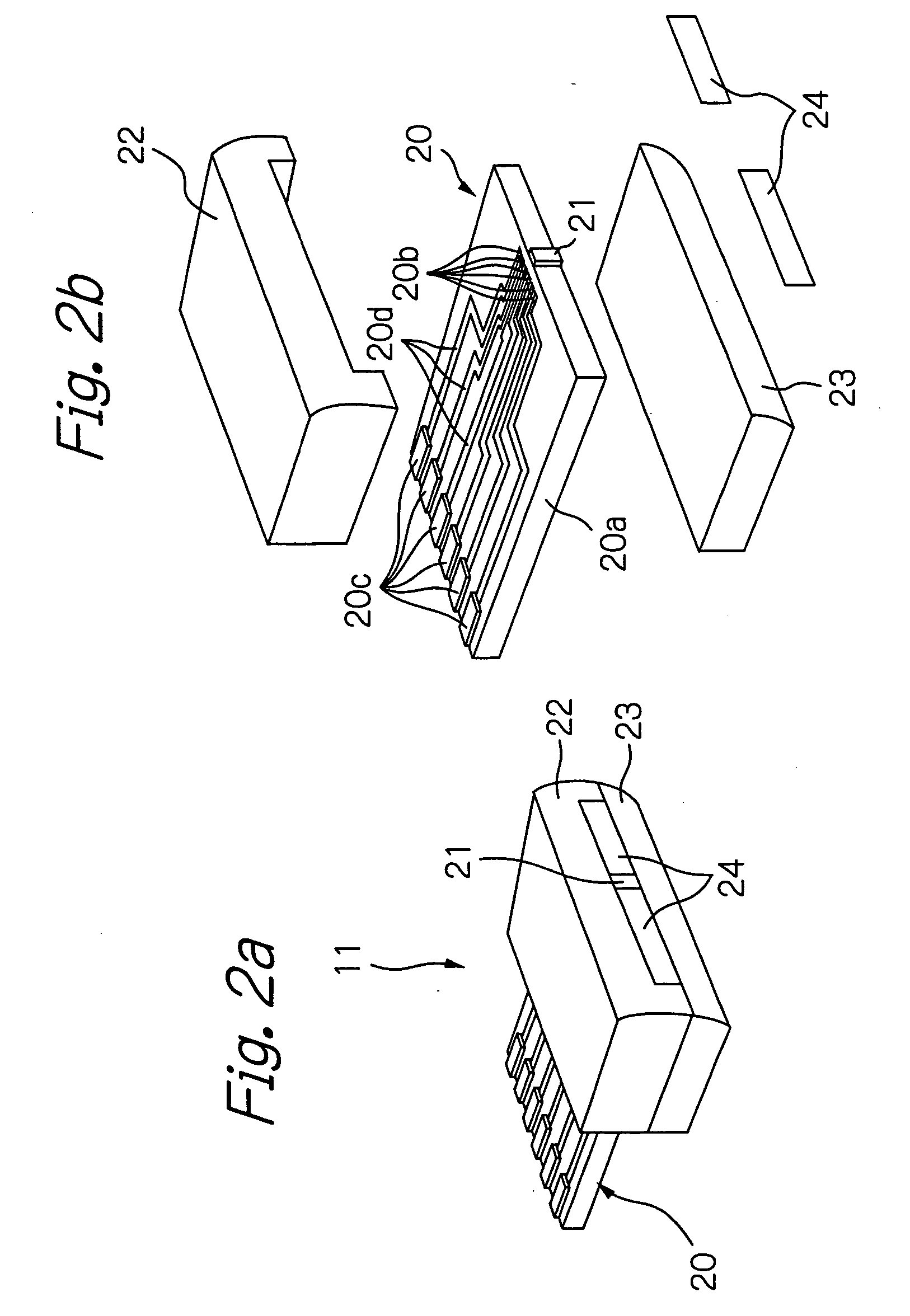
[0037]FIGS. 2a and 2b are an obli...


PUM

PropertyMeasurementUnit
lengthaaaaaaaaaa
thicknessaaaaaaaaaa
lengthaaaaaaaaaa

Abstract

A magnetic sensor for an encoder has a sliding surface and detects magnetic field by keeping the sliding surface in contact with a surface of a magnetic medium to which a magnetic pattern with a predetermined magnetization pitch is recorded. The magnetic sensor includes a plurality of MR elements laminated with each other in a direction parallel to a direction of the magnetization pitch of the magnetic medium. Between two of the MR elements an insulation layer is sandwiched. Each of the MR elements has a plurality of linear sections.

Description

PRIORITY CLAIM [0001] This application claims priority from Japanese patent application No. 2004-207013, filed on Jul. 14, 2004, which is incorporated herein by reference. BACKGROUND OF THE INVENTION [0002] 1. Field of the Invention [0003] The present invention relates to a magnetic sensor for an encoder, provided with a plurality of magnetoresistive effect (MR) elements. [0004] 2. Description of the Related Art [0005] U.S. Pat. No. 4,594,548 and Japanese patent publication No. 10-160511A disclose typical magnetic encoders used for position detection, displacement detection or rotation detection. Each of these encoders has a magnetic medium with a certain magnetization pattern formed by the horizontal magnetization recording method, and a magnetic sensor with MR elements each having a sensing plane in parallel with the surface of the magnetic medium to sense a plane direction or horizontal direction component of the horizontally recorded magnetic field from the magnetic medium. Beca...

Claims


Application Information

Patent Timeline
Patent Type & Authority Applications(United States)
IPC IPC(8): G11B5/33G11B5/127
CPCB82Y10/00B82Y25/00G11B2005/3996G11B5/3948G11B5/3909
Inventor SHOJI, SHIGERU
Owner TDK CORPARATION
Why Eureka
Try Eureka