Stereo image measuring device

Inactive Publication Date: 2006-01-19
KK TOPCON
View PDF3 Cites 14 Cited by
  • Summary
  • Abstract
  • Description
  • Claims
  • Application Information

AI Technical Summary

Benefits of technology

[0031] For an area of bad image correlation, interpolation is performed by the measurement of the reflectorless TS and, further, by setting its measurement value as an initial value, the area of measurement can be finer an

Problems solved by technology

However, in such a conventional method, image correlation processing must be carried out even for each image having different resolution, thus necessitating a great deal of time for its arithmetic operation.
In the conventional case, if a measuring error occurs, the operation of repeating the image correlation processing must be carried out by specifying the place of the measuring error again by an operator, thereby necessitating much labor and time for measurement and correction.
Also, conventionally, when the tree-dimensional measurement and analysis are needed at a natural disaster site or a place requiring emergency attendance or the like, there may be such cases where enough time may not be provided for measurement by the total station or the like at the actual site, measurement may be impossible, only photographs of the place may be taken, and the like.
However, this method necessitates a great deal of time for measurement, because the measurement is carried out while driving the TS by a motor.
Other problems have included the impossibility of measurement caused by the

Method used


Image

  • Stereo image measuring device
  • Stereo image measuring device
  • Stereo image measuring device

Examples


Embodiment Construction

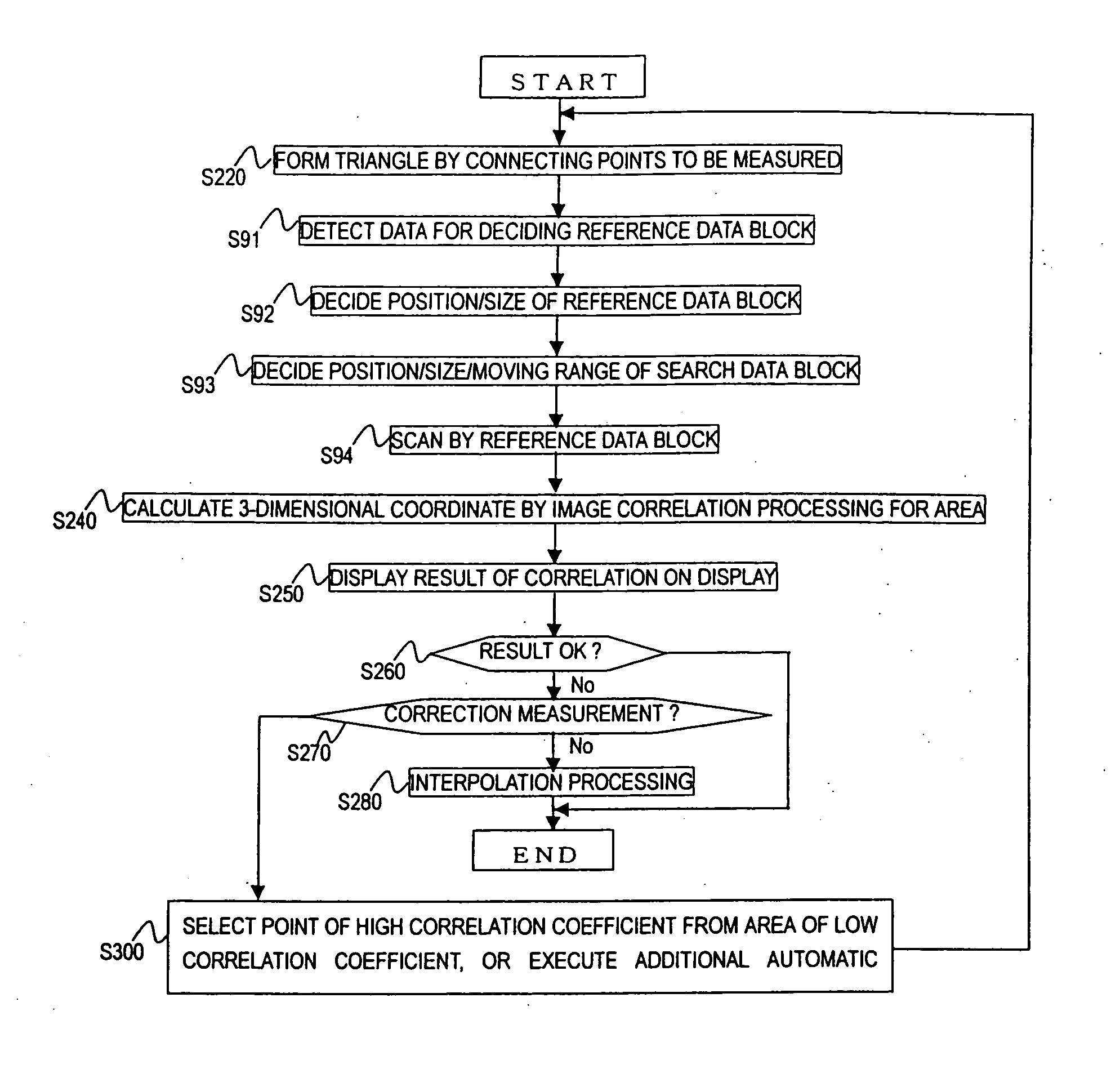
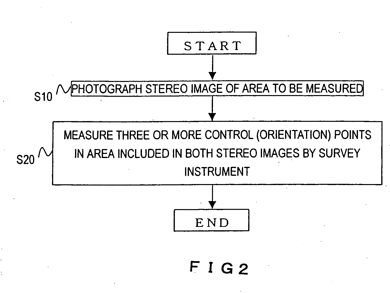
[0059] Next, description will be made of the preferred embodiments of the present invention with reference to the accompanying drawings.

A: Hardware

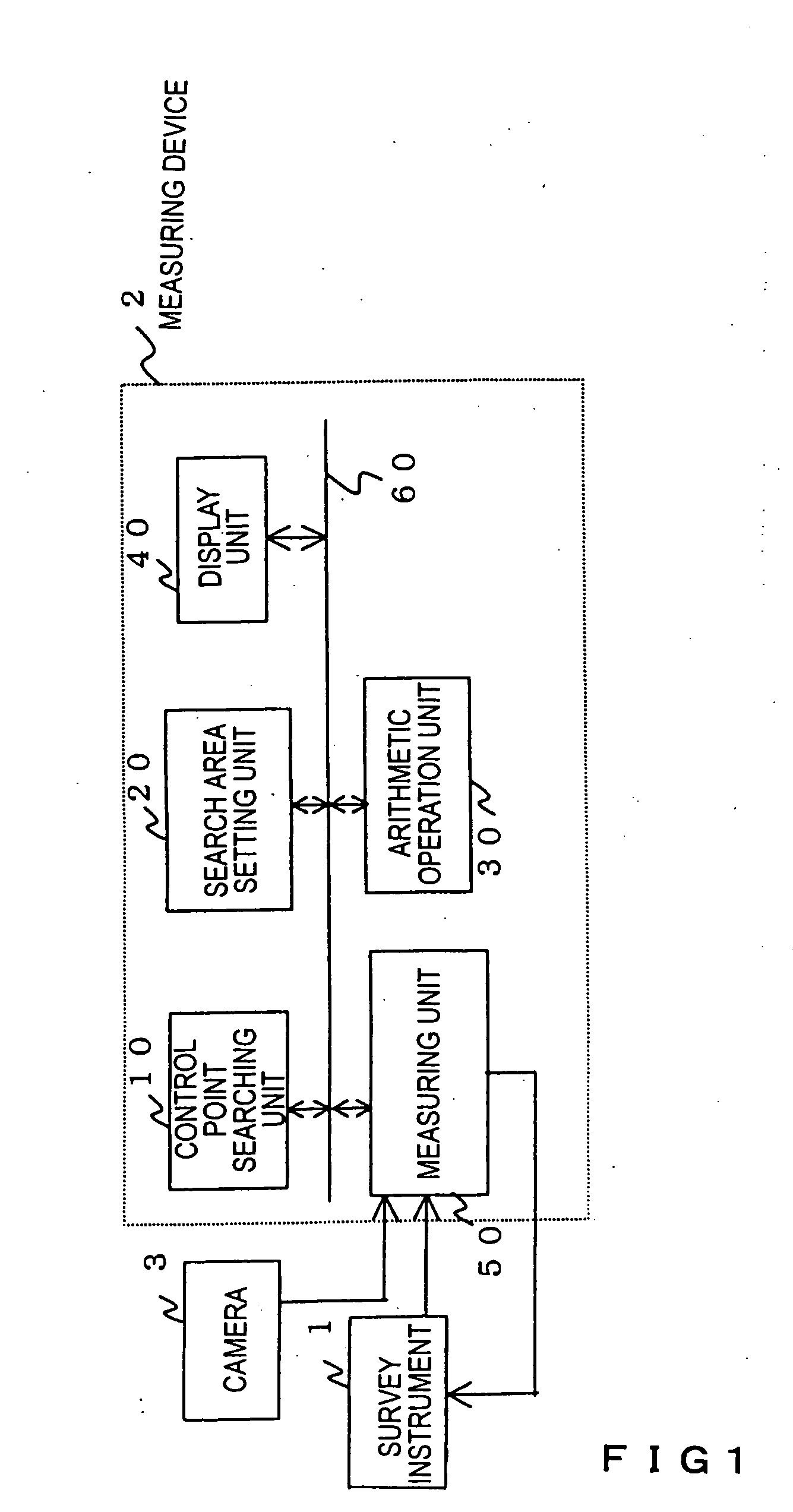
[0060]FIG. 1 is a block diagram showing the entire measuring device of the invention.

[0061] This system comprises a survey instrument 1, a measuring device 2, and a camera 3. The measuring device 2 includes a control point searching unit 10, a search area setting unit 20, an arithmetic operation unit 30, a display unit 40, a measuring unit 50, and a bus 60. These components, i.e., the control point searching unit 10, the search area setting unit 20, the arithmetic operation unit 30, the display unit 40 and the measuring unit 50 are loaded on, for example a personal computer, and interconnected through the bus 60.

[0062] The survey instrument 1 is used to measure several control points on site. This instrument is not necessary when measurement is performed by obtaining a stereo image having several control points contained therein befo...


PUM


Abstract

The present invention discloses a stereo image measuring device capable of carrying out high-speed and highly reliable three-dimensional measurement for a stereo image, easily correcting any omitted measurement, measurement errors or the like, and achieving a much higher speed, efficiency and reliability for measurement as a whole. A survey instrument measures a number of control points on site. A camera is, for example a digital camera, a film camera or the like. A control point search unit executes correlation between a control point measured beforehand by the instrument survey and an image. A search area setting unit sets a search area to be used for image correlation processing based on the control points correlated by the control point search unit, and sets respective data blocks, i.e., a reference data block and a search data block. An arithmetic operation unit executes orientation calculation, and image correlation processing (stereo matching) for the search area set by the search area setting unit. A display unit is a stereo monitor, a personal computer monitor or the like providing stereoscopic vision. A measuring unit executes additional measurement when the result of correlation processing is not satisfactory.

Description

[0001] The present application is a continuation of U.S. application Ser. No. 09 / 817,287, filed Mar. 27, 2001, the entire contents of which is incorporated herein by reference.BACKGROUND OF THE INVENTION [0002] The present invention relates to a stereo image measuring device and, more particularly, to a device for measuring a three-dimensional image from a stereo image. Throughout the specification, “off-line measurement” means executions of image photographing, for example, at a measuring site, and of operations other than the photographing at a different calculation and analyzing site. On the other hand, “on-line measurement” means executions of image measuring, and also of displaying of a three-dimensional image, for example, at a measuring site. [0003] In the conventional art of digital photogrammetry, three-dimensional measurement and analysis from an obtained digital image have been carried out in the following manner. First, orientation is carried out based on several imprint...

Claims


Application Information

Patent Timeline
IPC IPC(8): G06K9/00G01C11/06G06V10/24H04N13/239
CPCG01C11/06G06K9/32H04N13/0239G06T2207/20016G06T7/0075G06T2207/10012H04N2013/0081G06T7/593H04N13/239G06V10/24
Inventor KOCHI, NOBUOOTANI, HITOSHIITO, TADAYUKI
Owner KK TOPCON
Why Eureka
Try Eureka