
Optical fiber, evaluation and fabrication method thereof

a technology of optical fiber and fabrication method, applied in the field of single-mode optical fiber, can solve the problems of increasing transmission loss, difficult transmission in the vicinity of this wavelength, and prone to more residues at higher cooling rate, and achieve the effect of increasing the electron spin density of porous

Active Publication Date: 2006-01-19
FURUKAWA ELECTRIC CO LTD
View PDF3 Cites 20 Cited by
  • Summary
  • Abstract
  • Description
  • Claims
  • Application Information

AI Technical Summary

Benefits of technology

[0020] Further, the present invention provide a method for evaluating the hydrogen resistance of an optical fiber obtained by drawing an optical fiber preform to form an optical fiber comprising a core of a silica glass doped with at least germanium and a cladding of a silica glass surrounding it, and treating the optical fiber with hydrogen or deuterium to diffuse hydrogen molecules or deuterium molecules in the optical fiber by exposing the optical fiber to an atmosphere containing hydrogen or deuterium. The evaluation method is to evaluate the hydrogen-proof characteristic of the optical fiber by evaluating an increased amount in an electron spin density in the optical fiber after the hydrogen treatment or the deuterium treatment in comparison to that before the hydrogen or deuterium treatment by measuring the glass regions of the optical fibers before and after the hydrogen or deuterium treatment by ESR for the electron spin densities of PORs.

Problems solved by technology

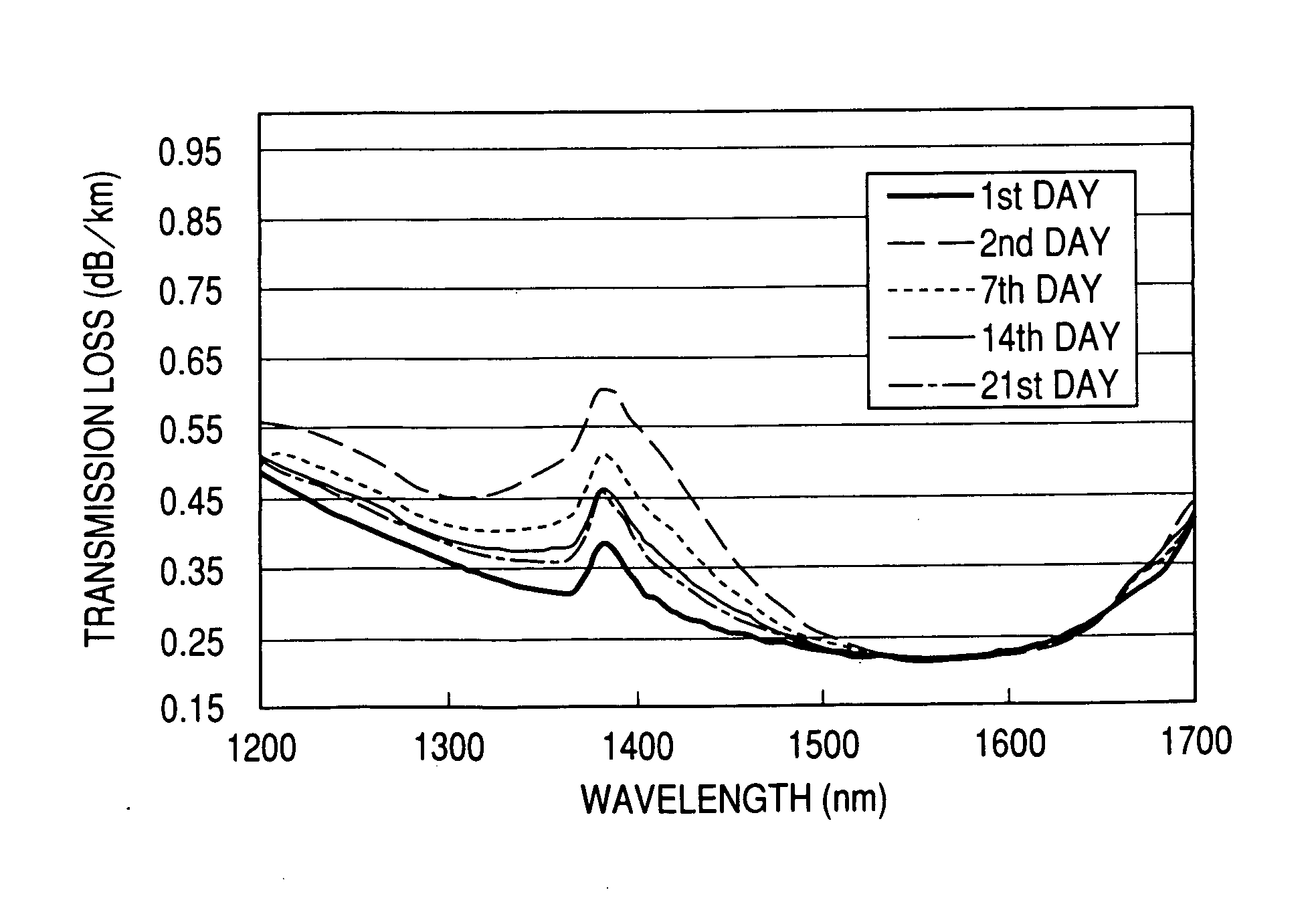
On the other hand, since a conventional optical fiber is often contaminated with OH groups as an impurity, which has an absorption peak at the wavelength of approximately 1385 nm, transmission in the vicinity of this wavelength is difficult.
Diffusion of hydrogen into the optical fiber brings about a reaction of the NBOHC and hydrogen, causing the increase in the transmission loss.
A higher cooling rate is prone to the more residues.
The absorption peak is unstable and prone to decrease with lapse time; however, the observation in a very long lapse time is needed for guaranteeing the fiber quality, thus presenting a great obstacle to fabricating an optical fiber.

Method used


Image

  • Optical fiber, evaluation and fabrication method thereof
  • Optical fiber, evaluation and fabrication method thereof
  • Optical fiber, evaluation and fabrication method thereof

Examples


examples

[0025] Hereinafter, the present invention will be illustrated by way of examples.

[0026] A. Fabrication of an Optical Fiber

[0027] 1. An Optical Fiber for a Fabrication Object

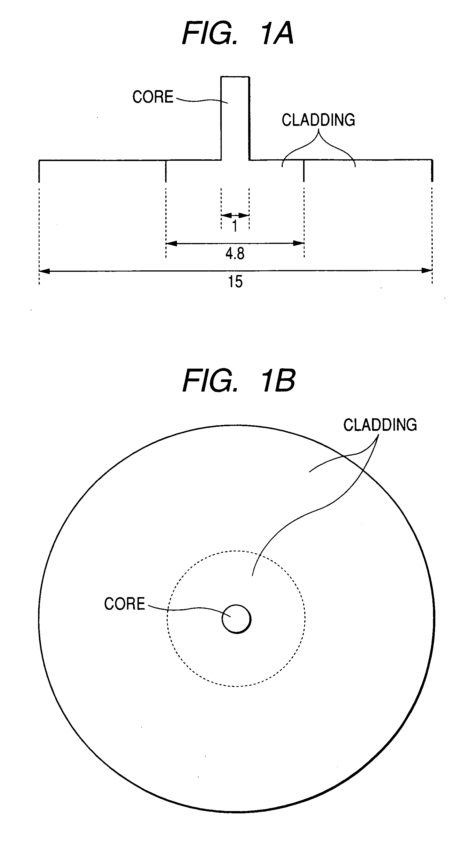
[0028] An optical fiber according to the present invention may have various refractive index profiles. However, for illustrating the gist of the present invention as simply as possible, the examples employed a single mode fiber (SMF) having a zero dispersion wavelength in a 1.3-μm band as a production kind, and a most common refractive index profile of a step index fiber in which a core is covered with a cladding as shown in FIG. 1(A). The diameter of the cladding was the most common at approximately 125 μm, and that of the core was approximately 8.3 μm.

[0029] 2. Fabrication of an Optical Fiber Preform

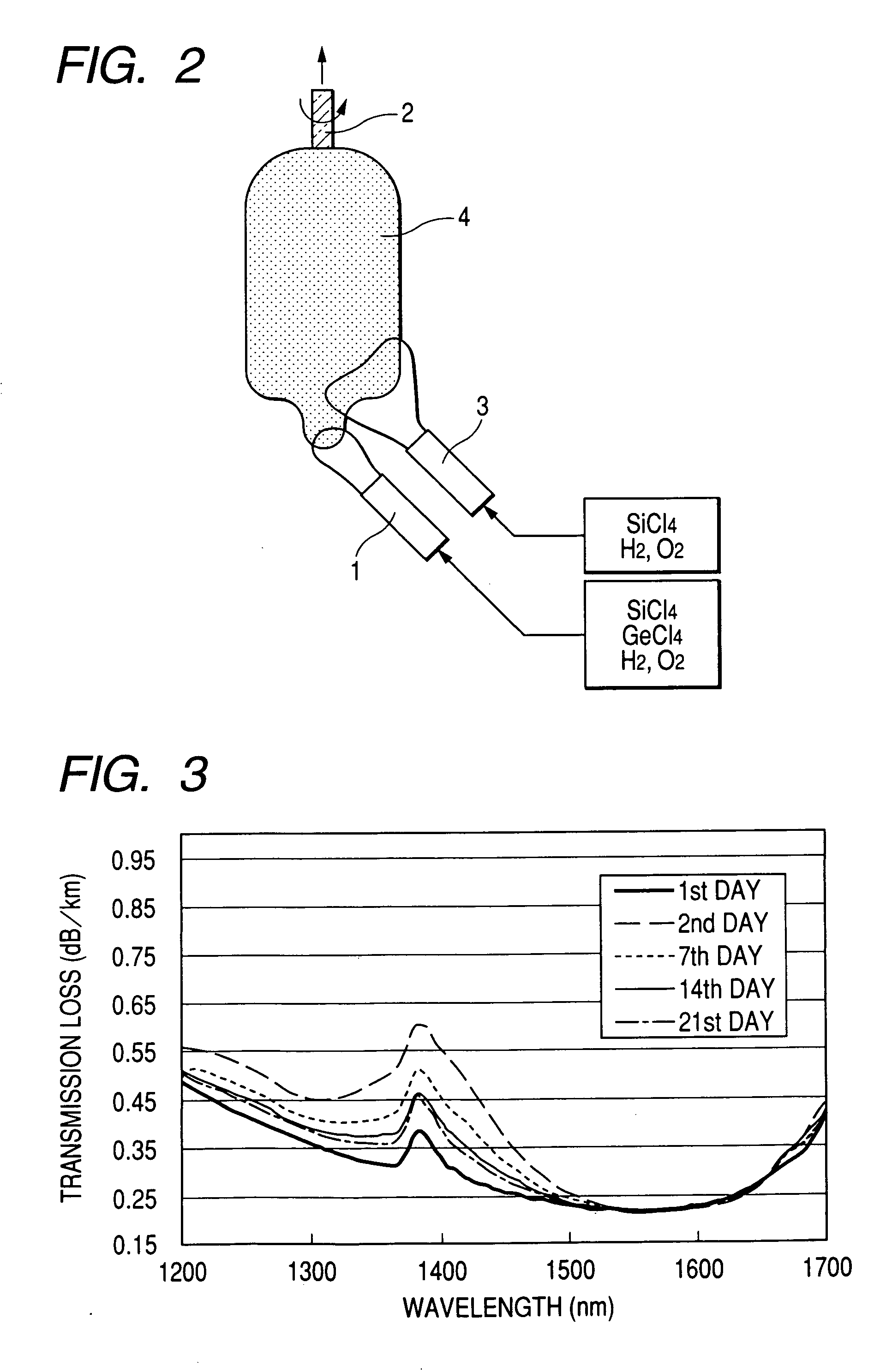
[0030] An optical fiber preform was fabricated by vapor-phase axial deposition (VAD) method as shown in FIG. 2. A porous preform 4 was formed on a rotating target rod 2 by blowing a soot from a hydrolysis burne...


PUM

PropertyMeasurementUnit
outer diameteraaaaaaaaaa
wavelength rangeaaaaaaaaaa

Abstract

An optical fiber having a small increase in loss at a wavelength of approximately 1400 nm involved in a deuterium treatment is provided, and an evaluation method to decide whether an optical fiber is that having such a loss increase, and a fabrication method of an optical fiber having a small increase in such a loss are also provided. An optical fiber according to the present invention comprises a core composed of a silica glass doped with at least germanium and a cladding composed of a silica glass surrounding it. The optical fiber is exposed to an atmosphere containing hydrogen or deuterium to diffuse hydrogen molecules or deuterium molecules in the optical fiber, and after that, the outer periphery of the glass region of the optical fiber is etched to an outer diameter of 50 μm, and then the electron spin density of PORs is 1×10¹³ spins / g or less when the glass region is measured by the electron-spin resonance method.

Description

BACKGROUND OF THE INVENTION [0001] 1. Field of the Invention [0002] The present invention relates to a single mode optical fiber which has high reliability of a hydrogen-proof characteristic and is suitable for wavelength division multiplexing (WDM) transmission in 1310 nm to 1625 nm, a method of evaluating whether an optical fiber is of that sort, and a method of fabricating such an optical fiber. [0003] 2. Related Background Art [0004] Much development has been conducted on optical fibers used for WDM transmission. At first, development of optical fibers was focused on a 1.55-μm band (e.g., in the wavelength range of 1535 to 1570 nm), in which the transmission loss of an optical fiber composed of a silica glass becomes a minimum; at present, studies to broaden the wavelength range for use to 1310 nm through 1625 nm are being conducted. [0005] On the other hand, since a conventional optical fiber is often contaminated with OH groups as an impurity, which has an absorption peak at t...

Claims


Application Information

Patent Timeline
Patent Type & Authority Applications(United States)
IPC IPC(8): G02B6/02
CPCC03C4/0042G02B6/02C03C25/607C03C13/047
Inventor KURUSU, KAZUHIKOMORIDAIRA, HIDEYAISHIDA, YOSHINORI
Owner FURUKAWA ELECTRIC CO LTD
Learn More