Devices for reducing the dynamic range of signals in transmitters of communication systems

a technology of communication system and transmitter, applied in the field of transmitters in communication system, can solve the problems of reducing the dynamic range the most complex and expensive item of the power amplifier, and the disadvantageous wide dynamic range, so as to reduce the distortion power, reduce the dynamic range performance, and improve the correlation of correction values with the desired correction at the correction time

Inactive Publication Date: 2006-01-19
INTEL CORP
View PDF4 Cites 34 Cited by
  • Summary
  • Abstract
  • Description
  • Claims
  • Application Information

AI Technical Summary

Benefits of technology

[0078] The present invention permits employing an equivalent model that describes all stages of a transmitter for predicting a signal. As a result, the distortion of the signal can be reduced without reducing performance of the dynamic range. Overcorrection of the dynamic range can also be mitigated. Spectral characteristics of a correction signal are not modified since only the input signal of a forward filer is modified. Additionally, correspondence of correction values with a desired correction at correction times can be improved and distortion power can be reduced. Further, secondary peaks generated by a correction of an input signal can be reduced and, therefore a better reduction of the dynamic range can be obtained as compared with conventional devices. Individual carrier signals of a multi-carrier signal are also typically less distorted.

Problems solved by technology

The result of this sum is a Gaussian signal which disadvantageously has a wide dynamic range.
The device in the transmitter influenced most by a wide dynamic range of the generated signal is the power amplifier which, among other things, is the most complex and expensive item.
The result of this is that the power amplifier must be selected to be oversized with respect to the desired rms power; that a larger cooling system is required for the larger power amplifier since the efficiency of a power amplifier is very low; that the requirements for setting the operating point of the power amplifier are higher; and that the power consumption of the power amplifier is greater.
In summary, this is associated with greater expenditure and with higher costs for the operator of a mobile radio system.
However, the transmitter has a significant disadvantage which will be illustrated by means of an example.
The result of this is that unnecessary disturbances or distortions are introduced into a signal or a sequence.
Therefore, a significant disadvantage of the transmitter of FIG. 14B and of the precompensation device of FIG. 15, respectively, consists in that the precompensation device cannot distinguish when a correction of a sequence of a signal is required and when not, and, therefore, cannot effect an efficient reduction of the dynamic range of a signal in a transmitter without unnecessarily distorting the signal.
A disadvantage of the device for reducing the dynamic range of an OFDM signal in FIG. 16, therefore, consists in that with a very low threshold value of the dynamic range, overcorrection of the signal to be corrected occurs and the overcorrection introduces unnecessary noise into the signal to be corrected.
The problem of overcorrection is based on the fact that the tails of old pulses of the correction signal overlap new pulses.
A further disadvantage of the device consists in that possibly unwanted larger peaks are generated outside the correction times.
However, a disadvantage of the transmitter in FIG. 21 consists in that the multi-carrier signal has a dynamic range which is greater than the dynamic range of the individual carrier signals as is also shown in FIG. 13.
This makes it more difficult to meet the requirements for the multi-carrier power amplifier and it is necessary to reduce the wide dynamic range.
A disadvantage of selecting the single-carrier amplitude correction signals according to equation 7 consists in that they cause too great a distortion of the multi-carrier signal.
These signals have a dynamic range which fluctuates greatly and is in some cases wide and which leads to great complexity in the circuits, and particularly amplifiers, used in a transmitter.

Method used


Image

  • Devices for reducing the dynamic range of signals in transmitters of communication systems
  • Devices for reducing the dynamic range of signals in transmitters of communication systems
  • Devices for reducing the dynamic range of signals in transmitters of communication systems

Examples


Embodiment Construction

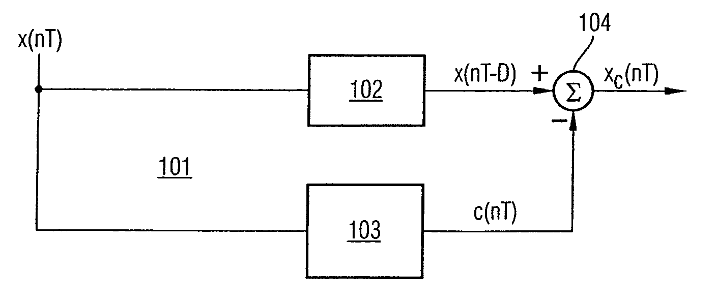
[0104]FIG. 1 shows an illustrative embodiment of a device for reducing the dynamic range of a signal according to the invention. The device is used for reducing the dynamic range of a signal at a first point in a signal processing direction in a transmitter of a communication system. The device is arranged at a second point along the signal processing direction within the transmitter which is located in front of the first point.

[0105] The communication system can be a mobile radio system and can be alternatively any wireless communication system such as, e.g., a wireless local area network (WLAN) or a wire-connected communication system. The transmitter is can be a transmitter of a base station of a UMTS mobile radio system. Signals in the transmitter are typically generated by a symbol source which maps bit streams to sequences of symbols, for example, by means of the QPSK modulation method and distributes these to physical channels by means of the WCDMA multiple access method. Th...


PUM


Abstract

A device reduces the dynamic range of a signal at a first point along a signal processing direction in a transmitter of a communication system. The device includes an input to which an input signal is applied, a correction prediction device, a delay device, an addition device, and an output. The correction prediction device generates a predictive signal based on the input signal which represents the prediction of the signal at the first point, and generates a correction signal from the predictive signal. The delay device generates an input signal delayed by a delay from the input signal, the delay taking into consideration the processing time in the correction prediction device. The addition device subtracts the correction signal from the delayed input signal in order to generate a corrected signal. The output provides the corrected signal at a second point in front of the first point.

Description

REFERENCE TO RELATED APPLICATIONS [0001] This application claims the benefit of the priority date of German application DE 10 2004 032 667.3, filed on Jul. 6, 2004, the contents of which are herein incorporated by reference in their entirety. FIELD OF THE INVENTION [0002] The present invention generally relates to transmitters in communication systems and particularly to devices for reducing the dynamic range of signals in transmitters of communication systems. BACKGROUND OF THE INVENTION [0003] Communication systems are frequently divided into wireless communication systems such as, e.g., mobile radio systems and wireless networks, and wire-connected communication systems. The Universal Mobile Telecommunications System (UMTS) is a current example of a mobile radio system. The basic architecture of a UMTS mobile radio system exhibits, among other things, mobile stations (User Equipment (UE)) and a radio access network (UMTS Terrestrial Radio Access Network (UTRAN)). The radio access...

Claims


Application Information

Patent Timeline
Patent Type & Authority Applications(United States)
IPC IPC(8): H04B17/00H03C1/62H04B1/707
CPCH04B1/0475H04B1/0483H04L27/2624H04L5/06H04B2201/70706
Inventor MARSILI, STEFANO
Owner INTEL CORP
Why Eureka
Try Eureka