Methods and apparatus for pivotable guide surfaces for arthroplasty

a technology of arthroplasty and pivoting guide surfaces, which is applied in the field of methods and equipment for bone resection, can solve the problems of inability or high resistance of the disclosed tool embodiment, and achieve the effects of improving the reproducibility of implant fit and alignment, facilitating use, and ensuring safety and work flow performan

Inactive Publication Date: 2006-01-19
PUGET BIOVENTURES
View PDF1 Cites 91 Cited by
  • Summary
  • Abstract
  • Description
  • Claims
  • Application Information

AI Technical Summary

Benefits of technology

[0010] The present invention utilizes a number of embodiments of cutting guide technologies loosely or directly based on Profile Based Resection (PBR). Preferably, the present invention is utilized for creating planar and/or curvilinear resection surfaces on or in the proximal tibial and other bones for prosthetic implants. The overriding objects of PBR technologies are to provide for significantly improved reproducibility of implant fit and alignment in a manner largely independent of the individual surgeon's manual skills, while providing for outstanding ease of use, economic, safety, and work flow performance.
[0011] The present invention may be utilized with a number of embodiments of alignment or drill guides to precisely and accurately determine the desired cutting guide location/orientation. In one embodiment, the guide structure is secured to the bone to be resected by fixation pins, although other techniques for referencing and aligning the guide structure are also encompassed by the present invention. The overriding objects of the embodiments are to precisely and accurately dictate the aforementioned locations and orientations while optionally enabling ease of use in conjunction with manually or Computer Assisted techniques, and while preferably enabling ease of use in minimally invasive procedures where surgical exposure and trauma are minimized.
[0012] The present invention utilizes a number of embodiments of cutting tools to remove bony materia...

Problems solved by technology

Specifically, many of the cutting tool embodiments disclosed are either incapable or highly resistant to dama...

Method used


Image

  • Methods and apparatus for pivotable guide surfaces for arthroplasty
  • Methods and apparatus for pivotable guide surfaces for arthroplasty
  • Methods and apparatus for pivotable guide surfaces for arthroplasty

Examples


Embodiment Construction

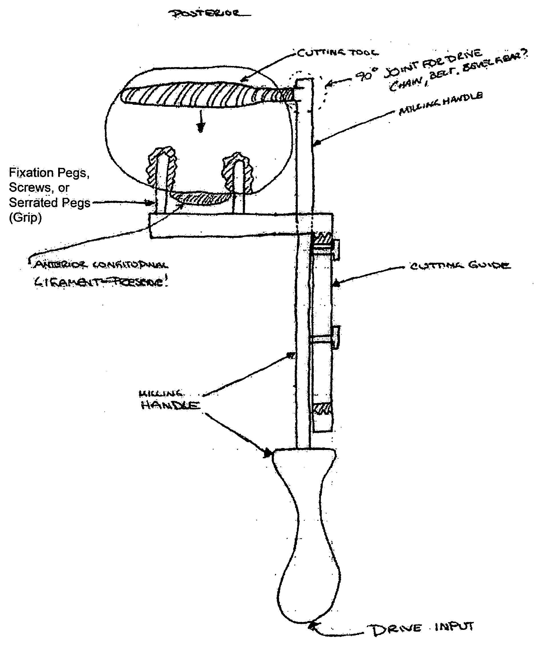
[0019] It should be noted that, in many of the figures, the cut surface created by the cutting tool in accordance with the techniques of the present invention are shown as having already been completed for the sake of clarity. Similarly, the bones may be shown as being transparent or translucent for the sake of clarity. The guides / pins, cutting tool, bones, and other items disclosed are may be similarly represented for the sake of clarity or brevity

FIGS. 1 through 4

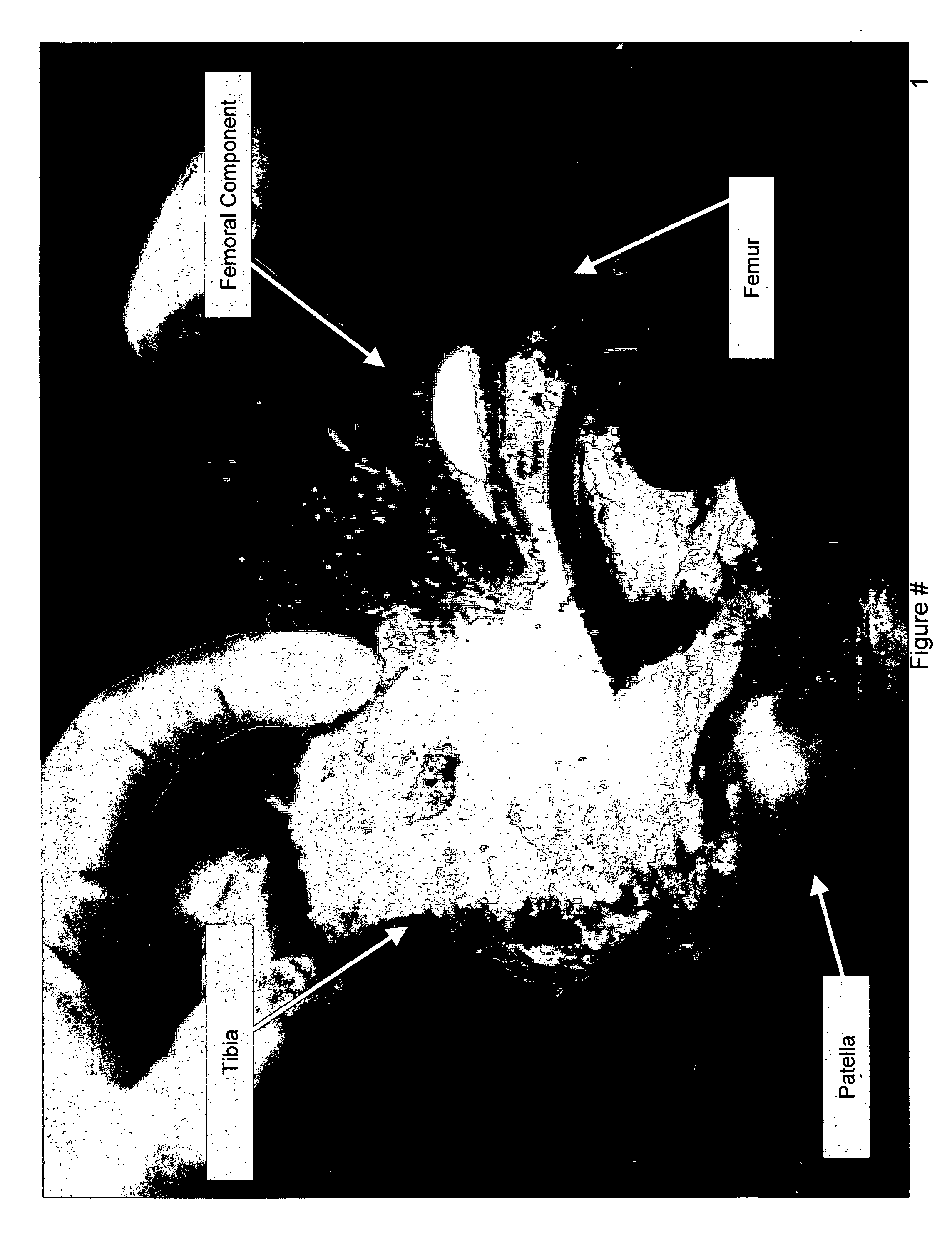
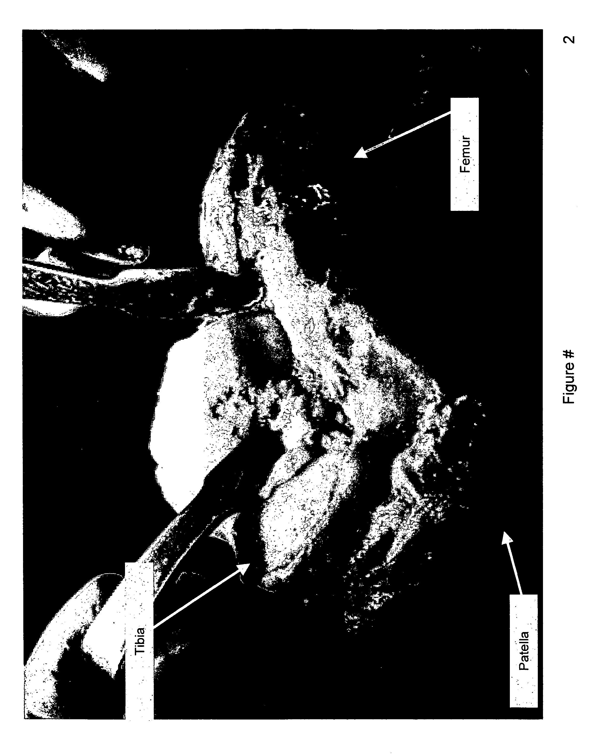
[0020]FIGS. 1 and 2 show conventional surgical exposures and instrumentation being utilized. FIG. 4 shows a reduced incision currently utilized in performing the current state of the art in ‘minimally invasive’ Unicondylar Knee Replacement.

FIGS. 5 through 11

[0021]FIGS. 5 through 11 describe an alignment guide / drill guide apparatus and / or drill guide / alignment guide techniques that can be used in conjunction with the present invention to align and secure the guide assembly via alignment pins. FIG. 5 shows a manually oper...


PUM


Abstract

Cutting guides, cutting tools, and soft tissue management techniques permit the use of pivoting guide surfaces to facilitate in controlling the sweep or arc of a cutting tool used in connection with resection and arthroplasty procedures. In accordance with one embodiment, a guide structure is provided with one or more guide pivot aperture(s) and one or more guide pivot reference surface(s) that mate with a bushing assembly controlling a cutting tool. The bushing assembly possesses a bushing reference plan which mates with the pivot reference surface(s) of the guide structure and a bushing pivot pin which mates with the guide pivot aperture(s) of the guide structure. In one embodiment, a bushing guide lumen is operably coupled to the guide structure for articulated and/or axial guidance of the cutting tool.

Description

CLAIM TO PRIORITY [0001] The present invention claims priority to U.S. Provisional Application No. 60 / 551,080, filed Mar. 8, 2004, entitled, “METHODS AND APPARATUS FOR PIVOTABLE GUIDE SURFACES FOR ARTHROPLASTY,” and U.S. Provisional Application No. 60 / 551,078, filed Mar. 8, 2004, entitled, “METHODS AND APPARATUS FOR MINIMALLY INVASIVE RESECTION,” and U.S. Provisional Application No. 60 / 551,096, filed Mar. 8, 2004, entitled, “METHODS AND APPARATUS FOR ENHANCED RETENTION OF PROSTHETIC IMPLANTS,” and U.S. Provisional Application No. 60 / 551,631, filed Mar. 8, 2004, entitled, “METHODS AND APPARATUS FOR CONFORMABLE PROSTHETIC IMPLANTS,” and U.S. Provisional Application No. 60 / 551,307, filed Mar. 8, 2004, entitled, “METHODS AND APPARATUS FOR IMPROVED CUTTING TOOLS FOR RESECTION,” and U.S. Provisional Application No. 60 / 551,262, filed Mar. 8, 2004, entitled, “METHODS AND APPARATUS FOR IMPROVED DRILLING AND MILLING TOOLS FOR RESECTION,” and U.S. Provisional Application No. 60 / 551,160, filed ...

Claims


Application Information

Patent Timeline
IPC IPC(8): A61B17/58
CPCA61B17/1671A61B17/1675A61B17/1757A61B17/1764A61F2310/00011A61F2/38A61F2/3859A61F2002/3895A61B2017/1602A61B90/10A61F2002/30649
Inventor HAINES, TIMOTHY G.
Owner PUGET BIOVENTURES
Why Eureka
Try Eureka