

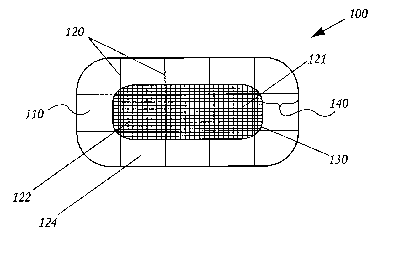
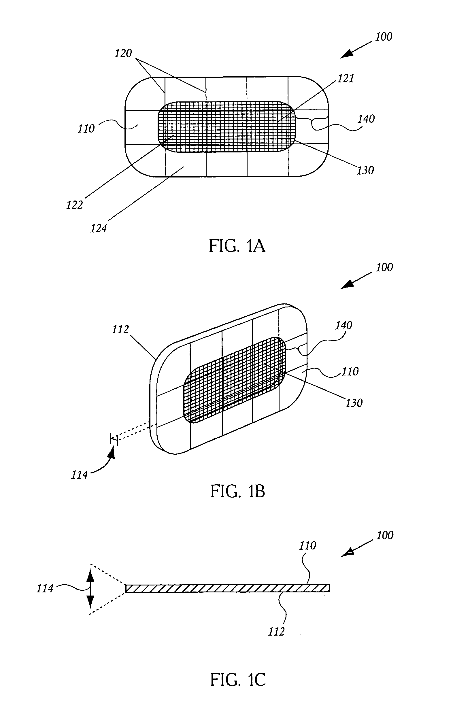
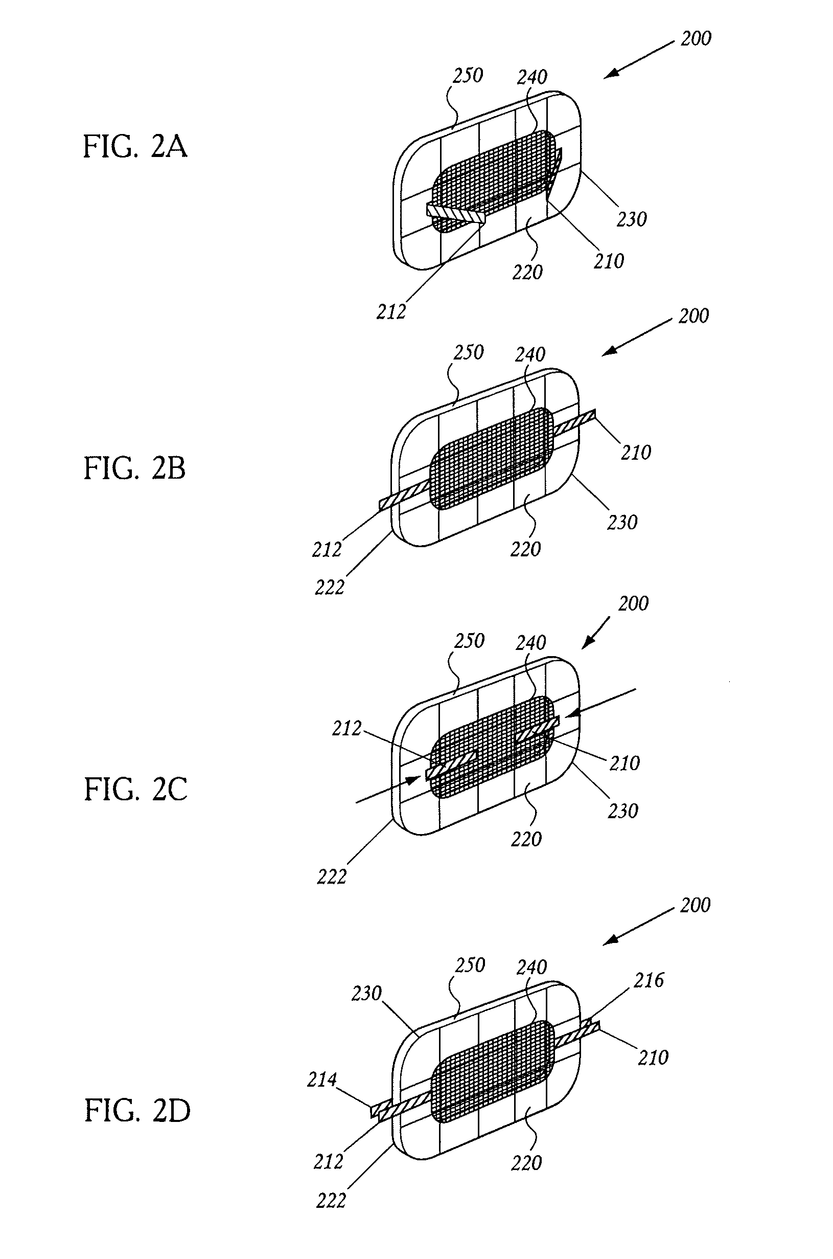
Emboli diverting devices created by microfabricated means
a technology of embolic material and micro-fabricated devices, which is applied in the field of implantable medical devices for filtering and/or diverting embolic material from blood, can solve the problems of greatest burden, disability, death and health care expenditure, and serious long-term physical and mental disability
- Summary
- Abstract
- Description
- Claims
- Application Information
AI Technical Summary
Benefits of technology
Problems solved by technology
Method used
Image

Examples
examples
I. Laser Micromachining
[0182] A substantially planar embolic filter was produced generally following the following laser cutting process. Using stock 25 micron stainless steel sheet metal, a 355 nm q-switched Nd:YVO4 laser system was used in conjunction with a direct write software program to produce a filter with 125-150 micron pores and 15-25 micron strut diameters. The struts were substantially ovoid and the diameter was consistently found to be in the range of 15-25 microns. The 25 micron thickness was amenable to folding of the device into a sheath. The porosity index of the device is between 75 and 78%.
[0183] A similar methodology was used to produce a filter with 10-15 micron strut diameters and pore sizes from 125-150 microns. The porosity index of this filter is approximately 79-83%.
II. Chemical and Electrochemical Processing
[0184] To further decrease the size of the struts and therefore increase the porosity of the filter and without having to deviate from the laser ...
PUM
 Abstract
Description
Claims
Application Information