Reservoir tank for vehicle brake system

Active Publication Date: 2006-01-26
ADVICS CO LTD
View PDF8 Cites 7 Cited by
  • Summary
  • Abstract
  • Description
  • Claims
  • Application Information

AI Technical Summary

Benefits of technology

[0014] Preferably, the partition plate is provided with at least two downward protrusions formed on a bottom surface thereof, the downward protrusions being provided around a vertical axis along which the float is movable, and circumferentially separated from each other by gaps that are large enough such that hydraulic fluid can flow therethrough, the downward protrusions being configured to abut the protrusions, thereby restricting the d

Problems solved by technology

Also, the retainer 9 adds to the number of parts, the number of ass

Method used


Image

  • Reservoir tank for vehicle brake system
  • Reservoir tank for vehicle brake system
  • Reservoir tank for vehicle brake system

Examples


Embodiment Construction

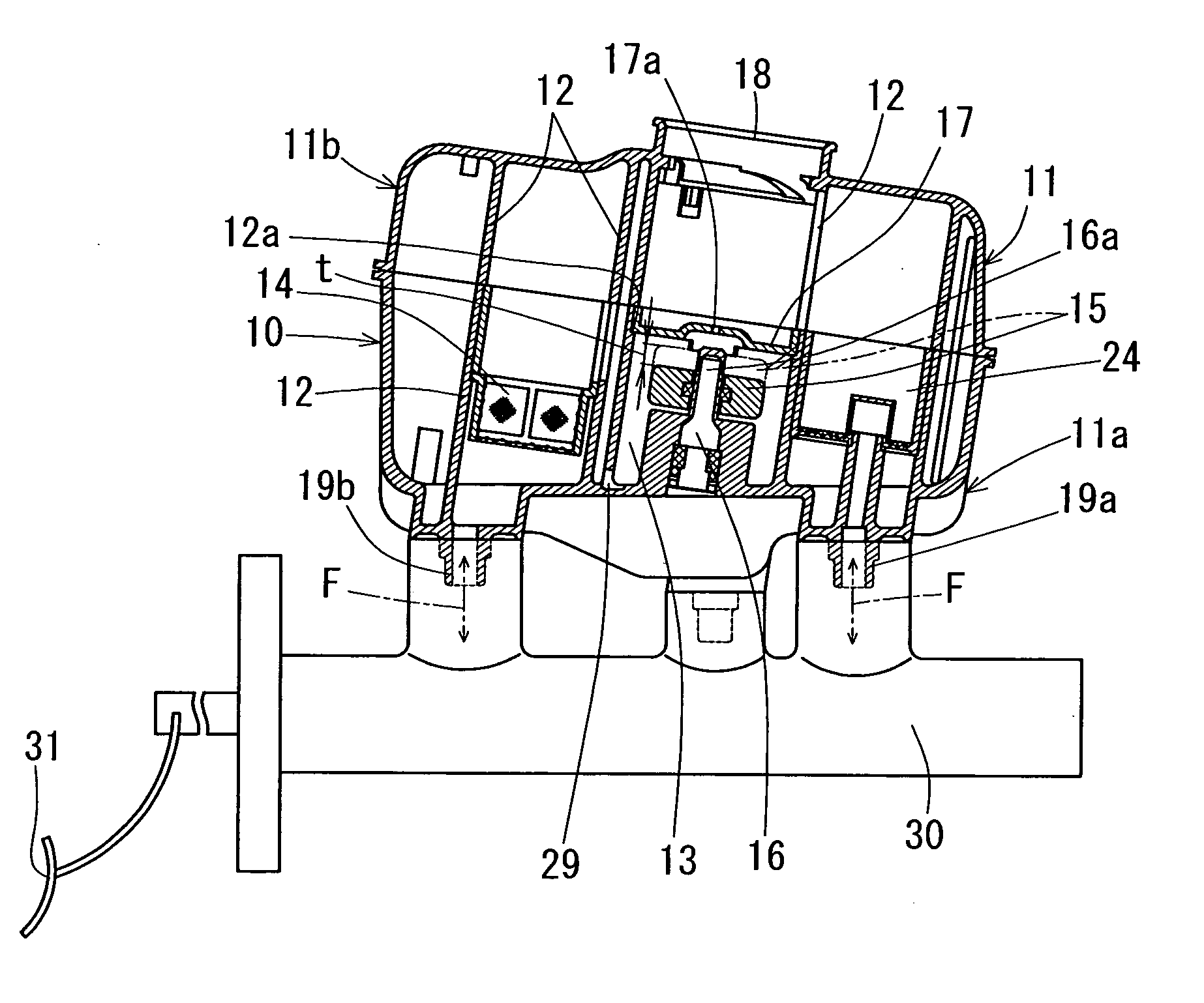
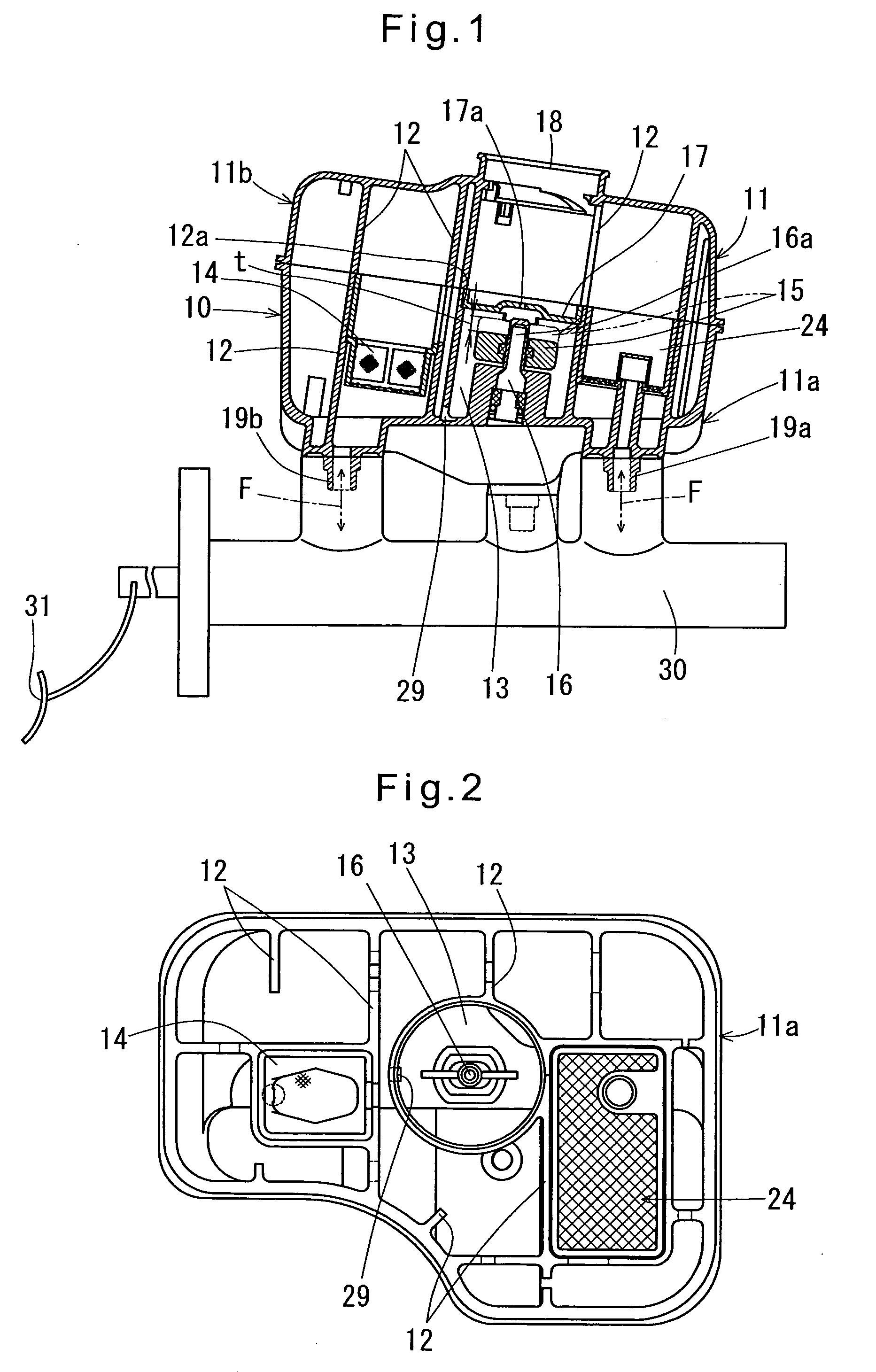
[0023] Now referring to FIGS. 1-5, the reservoir tank 10 embodying the present invention is used in a vehicle brake system for controlling brake hydraulic pressure of the vehicle brakes. The reservoir tank 10 includes a tank body 11 comprising a lower shell 11a and an upper shell 11b, which are both formed of a synthetic resin, and mounted to a master cylinder 30. The interior of the tank body 11 is divided into a plurality of chambers including a fluid level detecting chamber 13 by partition walls 12 to minimize pulsation of hydraulic fluid F. (In FIGS. 1 to 5, the partition walls 12 are partially not shown.) The upper shell 11b has on its top a hydraulic fluid supply port 18 integral with the upper shell 11b through which hydraulic fluid F is supplied into the tank body 11. The lower shell 11a has a port 19a through which hydraulic fluid F flows between the master cylinder30 and the reservoir tank 10, and a port 19b through which the hydraulic fluid F flows between the reservoir t...


PUM


Description

BACKGROUND OF THE INVENTION [0001] The present invention relates to a reservoir tank mounted to a master cylinder or a hydraulic booster of a vehicle brake system. [0002] A typical conventional reservoir tank 10 is shown in FIG. 6B, which comprises a tank body 1 comprising a lower shell 1a and an upper shell 1b, which are joined together by melting their mating surfaces with a hot plate H (FIG. 6A), putting the top shell 1b onto the lower shell 1a so that their molten mating surfaces contact each other, and allowing the mating surfaces to harden so as to be fixed to each other. [0003] The reservoir tank 10 includes partition walls 2 that divide the interior of the tank body 1 into a plurality of chambers, thereby minimizing pulsation of hydraulic fluid F in the tank body, a filter 4 provided in one of the chambers through which hydraulic fluid F flows into and out of the reservoir tank, and a float 5 and a fluid level sensor 6 provided in a fluid level detecting chamber 3. The flow ...

Claims


Application Information

Patent Timeline
IPC IPC(8): F16K33/00
CPCB60T11/26F16K33/00F16K27/02B60T17/225Y10T137/8342Y10T137/86187
Inventor HAYASHI, MITSUHARU
Owner ADVICS CO LTD
Why Eureka
Try Eureka