Pipe repair system and device

a pipe and repair system technology, applied in the direction of pipe joints, pipe/joints/fittings, pipe-joints, etc., can solve the problems of pipe rupture, high risk of pipe rupture, and uneven external diameter of pipe, so as to reduce the axial movement and contribute to the effect of pipe repair

Inactive Publication Date: 2006-01-26
BALL JEAN MAUREEN
View PDF4 Cites 4 Cited by
  • Summary
  • Abstract
  • Description
  • Claims
  • Application Information

AI Technical Summary

Benefits of technology

[0011] The second collar portion contains no such arcuate gripper members. All that is received in the annual internal recess in the second collar portion is a circular sealing member moulded from nitrite rubber, and application of high pressure grease to the hydraulic chamber established between the recess and the rubber sealing member is sufficient to cause the nitrile rubber sealing member to move into sealing contact against the external diameter of the old pipe section. The hydraulic pressure applied to compress the nitrite rubber sealing member against the external diameter of the old pipe section is preferably from 3000 to 8000 psi (2×10⁷ to 5.5×10⁷ pascals). At such high pressures, the nitrile rubber tends to extrude radially inwardly from the annual recess in which it is initially contained, and adopts a temporary semi-fluid characteristic which enables it to flow into, and there seal, any surface irregularities of the outside diameter of the old pipe around which the pipe connector is placed. An effective seal is therefore established between the pipe connector and the old pipe, but unlike the sealing between the first collar portion and the new pipe, the sealing between the second collar portion and the old pipe has no gripping component to restrain axial movement of the pipe connector relative to the old pipe. For reasons explained below, that is not a disadvantage and does in fact contribute to the effectiveness of the pipe repairs effected using the pipe connector.
[0014] The aspect ratio (radial depth to width) of the nitrile rubber sealing member is preferably of the order of 2:1, permitting the pipe connectors to be used with old pipe sections of a variety of sizes and in a variety of corroded conditions. By eliminating the grippers which were present in the first collar portion, the pipe connectors of the invention are of simpler construction than those of EP-B-727026 and EP-B-998643 and, much more importantly, the pipe connectors of the invention can be used to effect in situ repairs of a number of pipelines of different external diameters and in different stages of corrosion or decay. In the absence of gripper members associated with the second collar portion, the annular seal can extrude freely outwardly against the old pipe sections, while the gripper members associated with the first collar portions are effective securely to anchor the pipe connectors against axial movement. Significant tolerances, even radial gaps of up to 28 mm, can be accommodated between the second collar portions and the old pipe sections, since the inwardly extruded nitrile rubber seals can span and fill gaps up to that size.

Problems solved by technology

Particularly when the pipe is laid underground, there is a high risk of pipe rupture due to corrosion (especially in the case of metal pipes) or ground movement.
In climates suffering extremes of temperature, there is also the possibility of frost damage causing pipe rupture.
If a pipe has been underground or exposed to the elements for a considerable period, then its external diameter can be very uneven.
Some ductile iron pipes that have been buried underground for a large number of years, for example, can have surface rust presenting a flaky, uneven and unstable exterior surface to a depth of almost 15 mm.

Method used


Image

  • Pipe repair system and device
  • Pipe repair system and device
  • Pipe repair system and device

Examples


Embodiment Construction

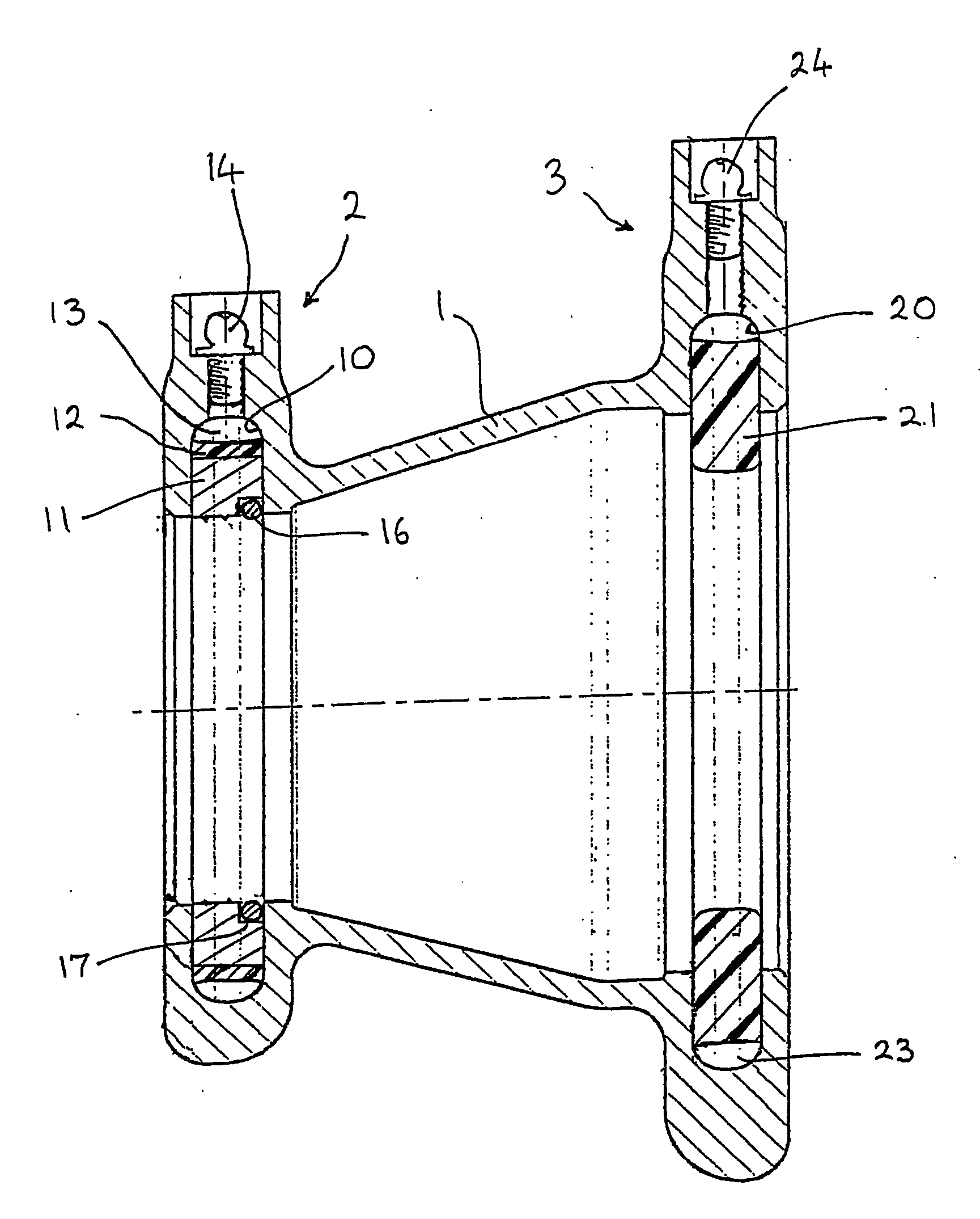
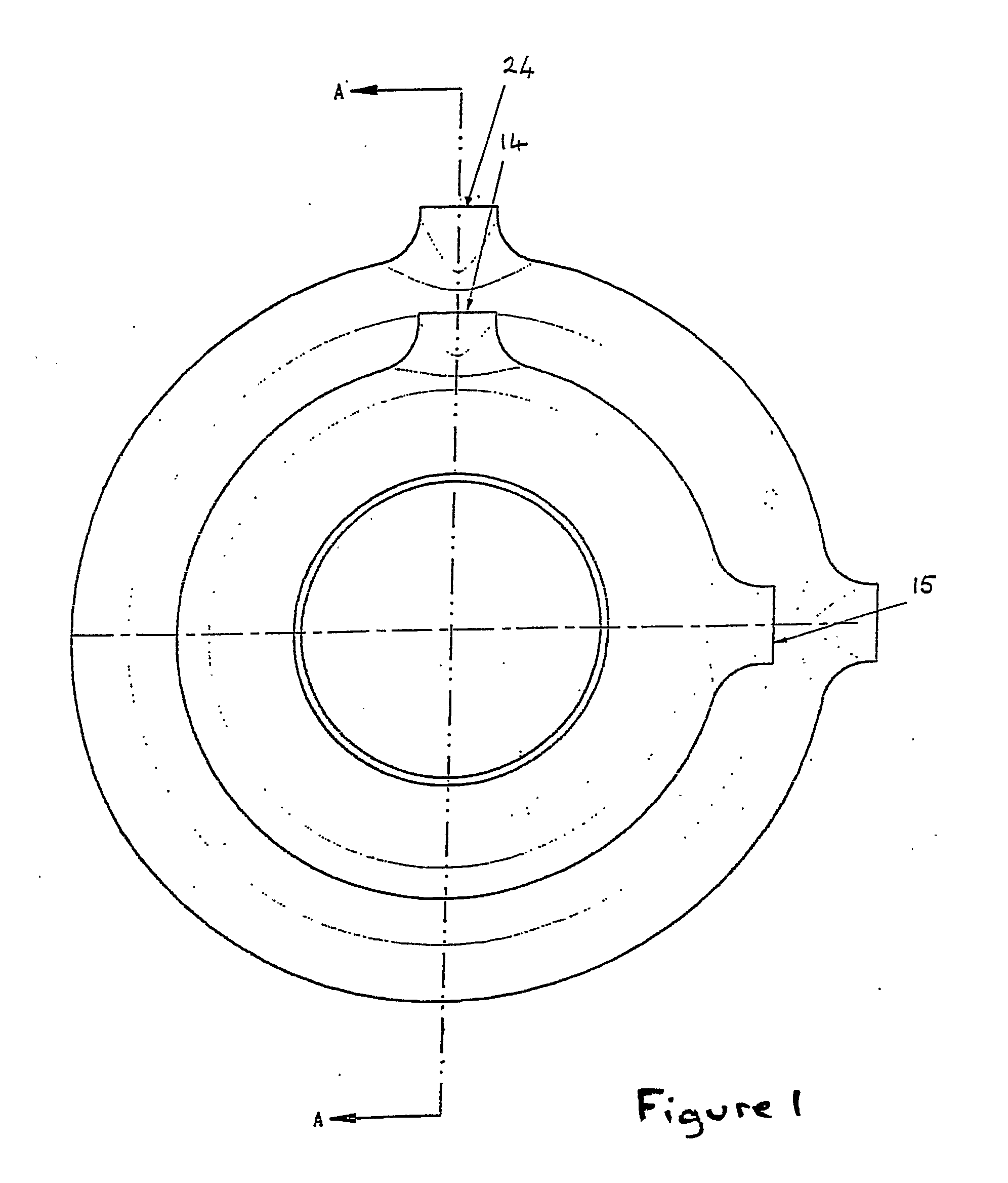
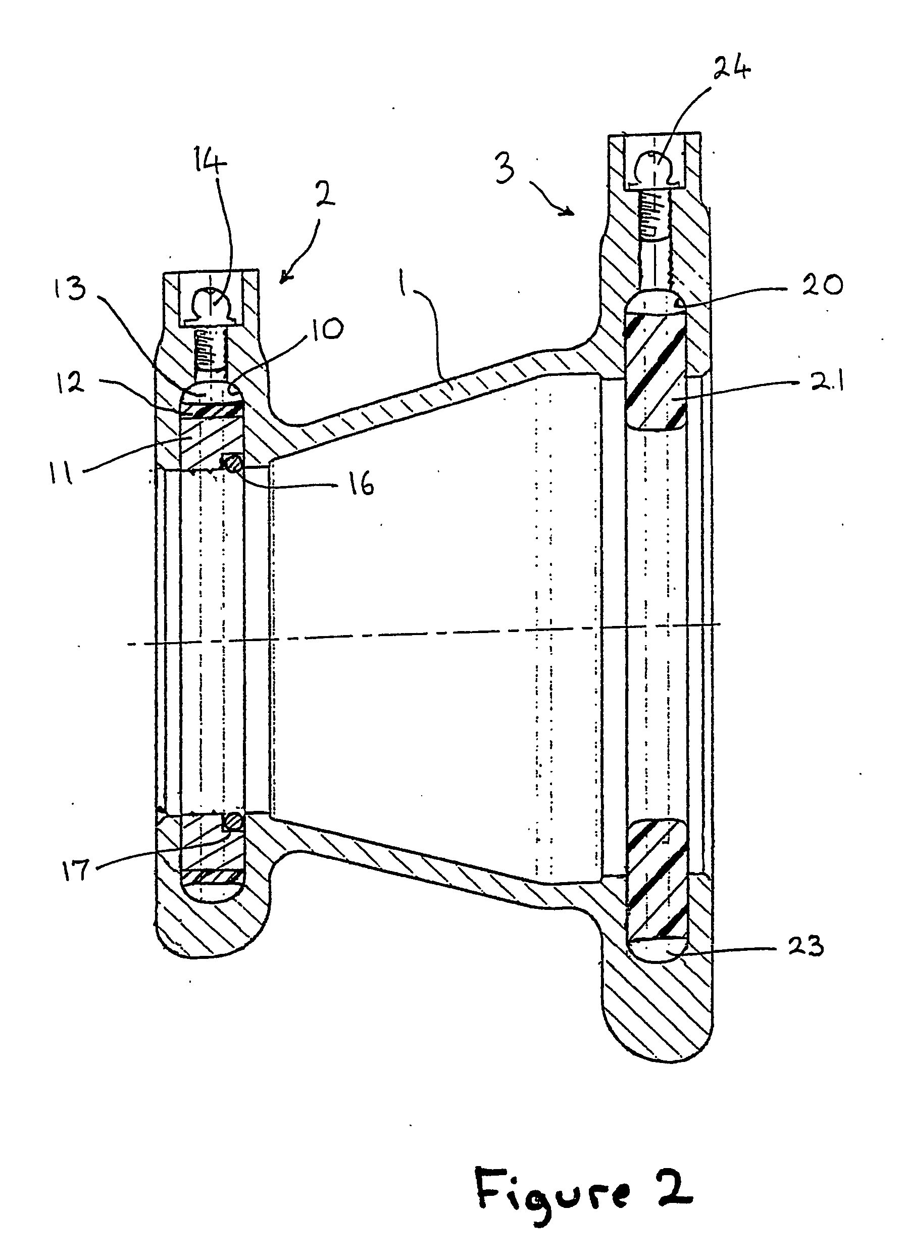
[0020] The coupling of FIGS. 1 and 2 comprises a sleeve portion 1 which is generally frustoconical in shape and extends from a first collar portion 2 to a second collar portion 3. The first collar portion 2 is for surrounding a new pipe section in use, and is as described in European Patent No. EP-B-727026. An annular groove 10 is formed on the internal surface of the collar 2 and houses a circular array of arcuate gripper members 11 surrounded by a sealing member 12. Between the sealing member 12 and the internal periphery of the groove 10 is formed a hydraulic chamber 13 which can be pressurised by the application of high pressure grease through a grease nipple 14. A release valve 15 offset by 90° from the grease nipple 14 permits release of the pressure from the hydraulic chamber 13 should that be necessary. An array of arcuate shims (not shown) is provided between the sealing member 12 and the arcuate gripper members 11, each shim bridging the gap between adjacent arcuate grippe...


PUM


Abstract

The invention provides a coupling member for use in the repair of pipes and pipelines of from 90 mm to 250 mm in diameter, such as those used for the pipeline transportation and delivery of domestic and industrial liquids such as water, gas, oil and other petrochemicals. Two coupling members are used for each repair. Each has a first collar portion for surrounding the new pipe section and a second collar portion for surrounding a cut end portion of the old pipe section, and the two pipe connectors are located with their respective first collar portions adjacent to one another and their respective second collar portions facing mutually outwardly towards the opposite ends of the new pipe section. Pressure chambers are formed between the annular grooves and the seal members of the first collar portions and between the annular grooves and the nitrile rubber sealing rings of the second collar portions.

Description

FIELD OF THE INVENTION [0001] The invention relates to a system and device for the quick and permanent repair of burst sections of pipe carrying household and / or industrial fluids such as water, gas, oil and other petrochemicals. BACKGROUND ART [0002] The above household and / or industrial fluids are normally transported underground or above ground in pipelines having pipe sizes of from 90 mm to 250 mm. The pipes are typically made from plastic, steel or ductile iron, and the fluids can be transported under pressure, typically at pressures up to 100 BAR. Particularly when the pipe is laid underground, there is a high risk of pipe rupture due to corrosion (especially in the case of metal pipes) or ground movement. In climates suffering extremes of temperature, there is also the possibility of frost damage causing pipe rupture. In all cases when a pipe or pipeline bursts, it is necessary to effect a repair as quickly as possible. Ideally the repair should be one that is permanent, so t...

Claims


Application Information

Patent Timeline
Patent Type & Authority Applications(United States)
IPC IPC(8): F16L55/18F16L17/03F16L17/10
CPCF16L17/10F16L25/14F16L37/62F16L37/00
Inventor BALL, JEAN MAUREEN
Owner BALL JEAN MAUREEN
Why Eureka
Try Eureka