Antenna module for mobile phone

a mobile phone and antenna module technology, applied in the field of radio telephony, can solve the problems of limited mobility of a traditional telephone, limited channelization frequency available, and inability to tolerate interruptions as easily, and achieve the effect of increasing the cost of basic mobile stations

Inactive Publication Date: 2006-01-26
NOKIA CORP
View PDF12 Cites 26 Cited by
  • Summary
  • Abstract
  • Description
  • Claims
  • Application Information

AI Technical Summary

Benefits of technology

[0023] The present invention provides a way to enable MRD in wireless communication systems without necessarily increasing the cost of basic mobile stations to the operator. To accomplish this objective, the present invention is directed to a detachable external antenna module for use with a wireless mobile station. The mobile station, which typically communicates on a radio frequency channel with a base station connected to the fixed infrastructure of a wireless communication network, may be able to receive transmission from the base station sent at lower power by applying mobile receive diversity (MRD).

Problems solved by technology

The mobility of a traditional telephone is limited by the wire connecting it to the network.
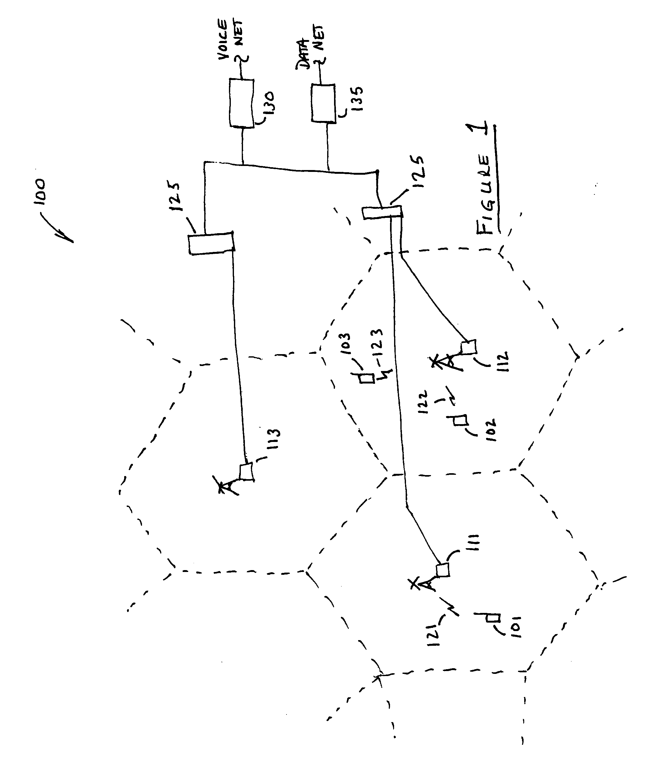
Environmental factors affecting the pairing of a base station to a mobile phone may include the level of traffic, with one base station communicating with a maximum number of mobiles, and may also include natural or man-made obstacles interfering with normal transmission.
In general, voice calls can tolerate much more error than data transmissions, but they take place in “real time” and therefore do not tolerate interruptions as easily.
Available frequencies for channelization are a limited resource, however, so the low power transmission enabled by the cellular network architecture enables frequencies to be reused in non-adjacent cells.
The time slots are of such duration and recur often enough that even a voice conversation transmitted in this way may appear uninterrupted.
In addition, regulatory agencies often require a limit on the aggregate power used for transmission in any given area.
Mobile phones, however, present a particular challenge in the field of receive (or transmit) diversity, because the space available for additional antennas is not unlimited.
Initially, however, mobile phones were quite expensive and only used by those who could either afford them or absolutely needed them.
Network capacity was limited and quality of service was often poor.
The existing infrastructure of several years ago could certainly not have supported the level of traffic that exists today.
Expense and the physical limitations referred to above, however, make universal application of MRD difficult.

Method used


Image

  • Antenna module for mobile phone
  • Antenna module for mobile phone
  • Antenna module for mobile phone

Examples


Embodiment Construction

[0035] FIGS. 1 though 9, discussed herein, and the various embodiments used to describe the present invention are by way of illustration only, and should not be construed to limit the scope of the invention. Those skilled in the art will understand the principles of the present invention may be implemented in any similar radio-communication device, in addition to those specifically discussed herein.

[0036] The present invention is directed to an antenna module for using in connection with a mobile phone that may be used to provide mobile receive diversity (MRD) while at the same time overcoming many of the disadvantages accompanying prior attempts to achieve this result.

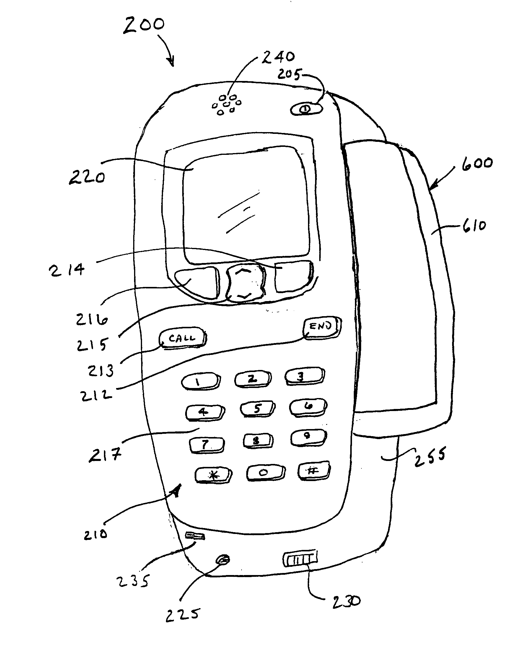
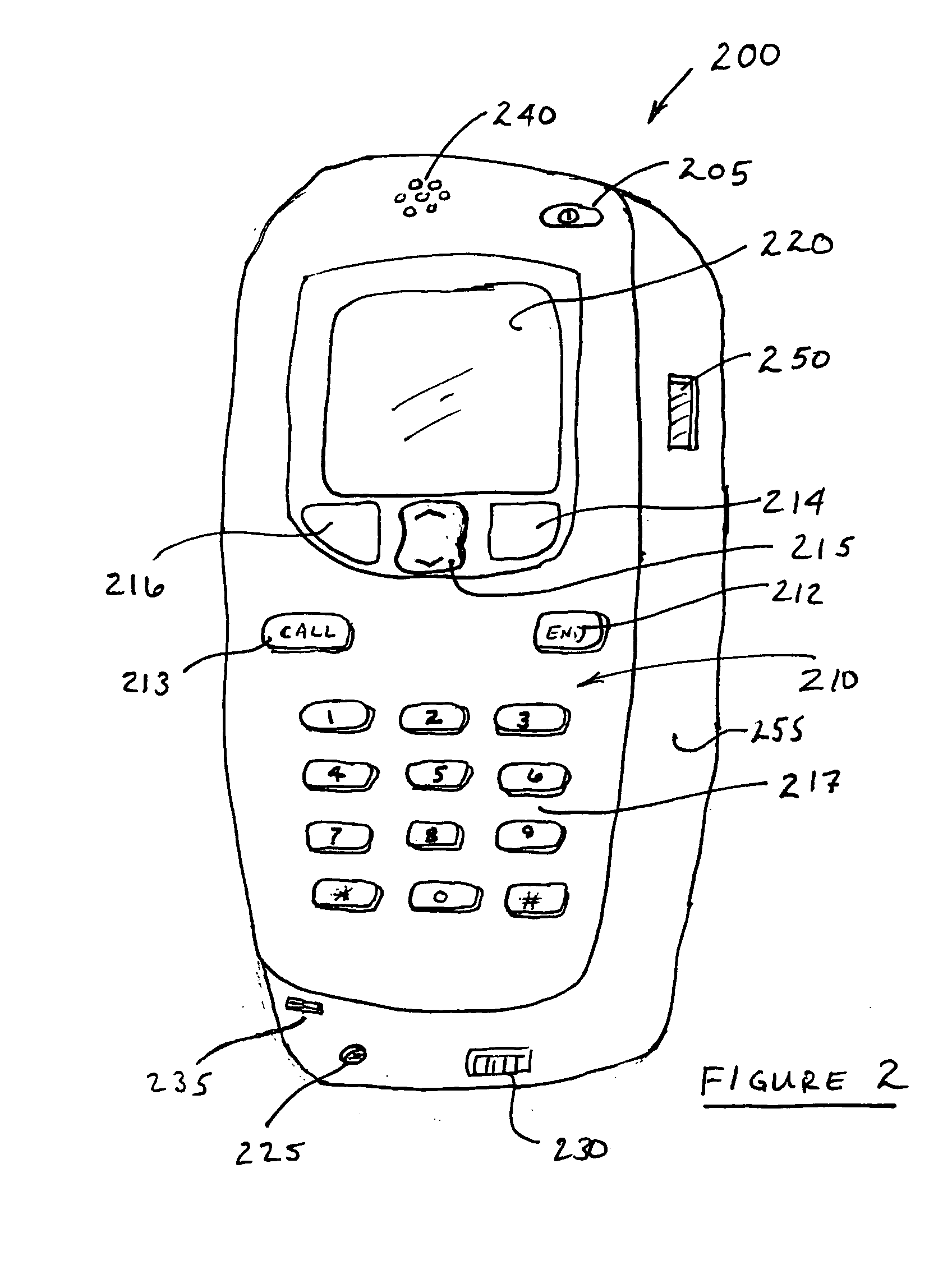
[0037]FIG. 3 is a simplified block diagram illustrating an antenna module 300 according to an embodiment of the present invention. Antenna module 300 includes an antenna element 305, which will provide diversity when used in conjunction with the internal antenna of a mobile phone (not shown in FIG. 3). Note that ant...


PUM


Abstract

An antenna module for use with a mobile telecommunication device such as a mobile phone. The antenna module includes an antenna element and, preferably, an RF (radio frequency) chain having receive circuitry and perhaps an analog-to-digital converter or other electrical components. Transmit circuitry may be present as well. The antenna module has a housing, in one or more parts, for supporting these components, and a jack through which power and data links can be formed. The jack may provide a means for adjusting the antenna so that its orientation relative to the mobile phone antenna may be altered.

Description

FIELD OF THE INVENTION [0001] The present invention relates generally to radio telephony, and more specifically to an external antenna module for a wireless mobile station that may be used to increase receive diversity on the downlink of a CDMA or W-CDMA wireless communication system. BACKGROUND OF THE INVENTION [0002] More and more people are using mobile telephones. A telephone is a device that converts sounds, such as a caller's voice, into electrical signals that can be transmitted to another telephone. The receiving telephone detects the transmitted signals and converts them back into sounds that another caller may hear. Typically, each of the telephones involved can both transmit and receive so that the callers may carry on a conversation. Traditional telephones are connected to a telephone network by a wire or cable through which the electrical signals are sent. The telephone network, generally speaking, is a system of interconnected wires and switches that create a transmiss...

Claims


Application Information

Patent Timeline
Patent Type & Authority Applications(United States)
IPC IPC(8): H01Q1/24
CPCH01Q1/088H01Q9/0407H01Q1/44H01Q1/243
Inventor KANNAN, ANANDBHATT, TEJAS
Owner NOKIA CORP
Why Eureka
Try Eureka