System and method to modify the spatial response of a pattern generator

a pattern generator and spatial response technology, applied in the field of lithography system, can solve the problem of defining the region of double exposure or no exposur

Inactive Publication Date: 2006-01-26
ASML HLDG NV
View PDF23 Cites 10 Cited by
  • Summary
  • Abstract
  • Description
  • Claims
  • Application Information

AI Technical Summary

Benefits of technology

[0012] A still further embodiment of the present invention provides a method comprising for modification of a spatial light modulator (SLM) to aid spatial stitching of images projected by the SLM onto a substrate comprising the steps of (a) directing a modifying device towards a surface of the SLM and (b) modifying a portion of the surface of the SLM to thereby change an optical response of the SLM in a controlled manner.

Problems solved by technology

However, any error in the distance the substrate is moved between exposures will lead to a finite region of either double exposure or no exposure on the substrate.

Method used


Image

  • System and method to modify the spatial response of a pattern generator
  • System and method to modify the spatial response of a pattern generator
  • System and method to modify the spatial response of a pattern generator

Examples


Embodiment Construction

[0023] While specific configurations and arrangements are discussed, it should be understood that this is done for illustrative purposes only. A person skilled in the pertinent art will recognize that other configurations and arrangements can be used without departing from the spirit and scope of the present invention. It will be apparent to a person skilled in the pertinent art that this invention can also be employed in a variety of other applications.

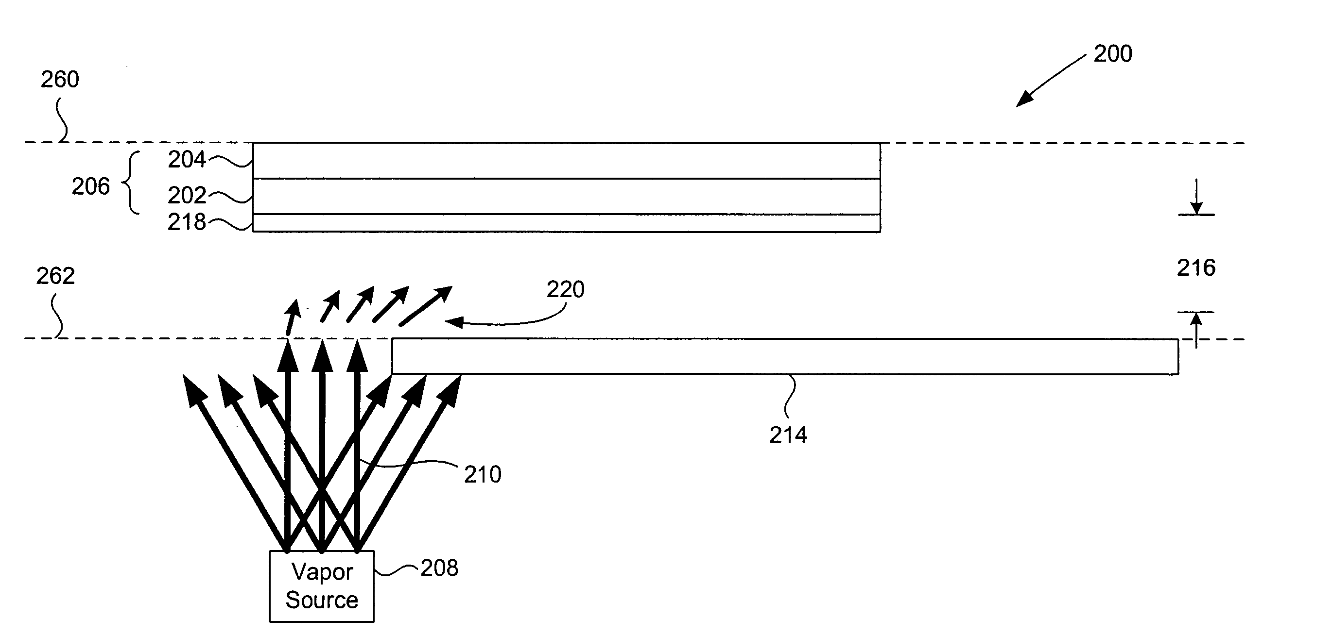
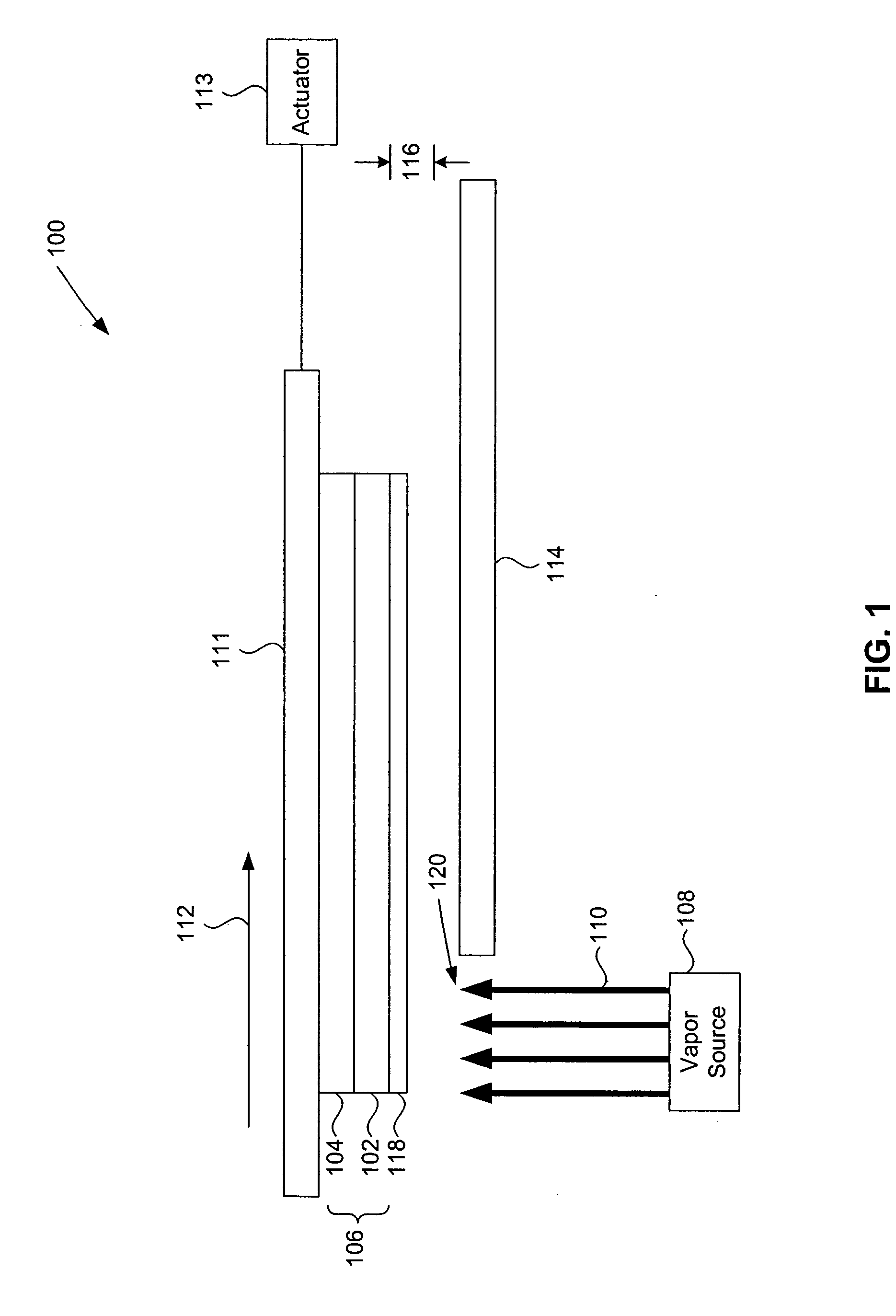
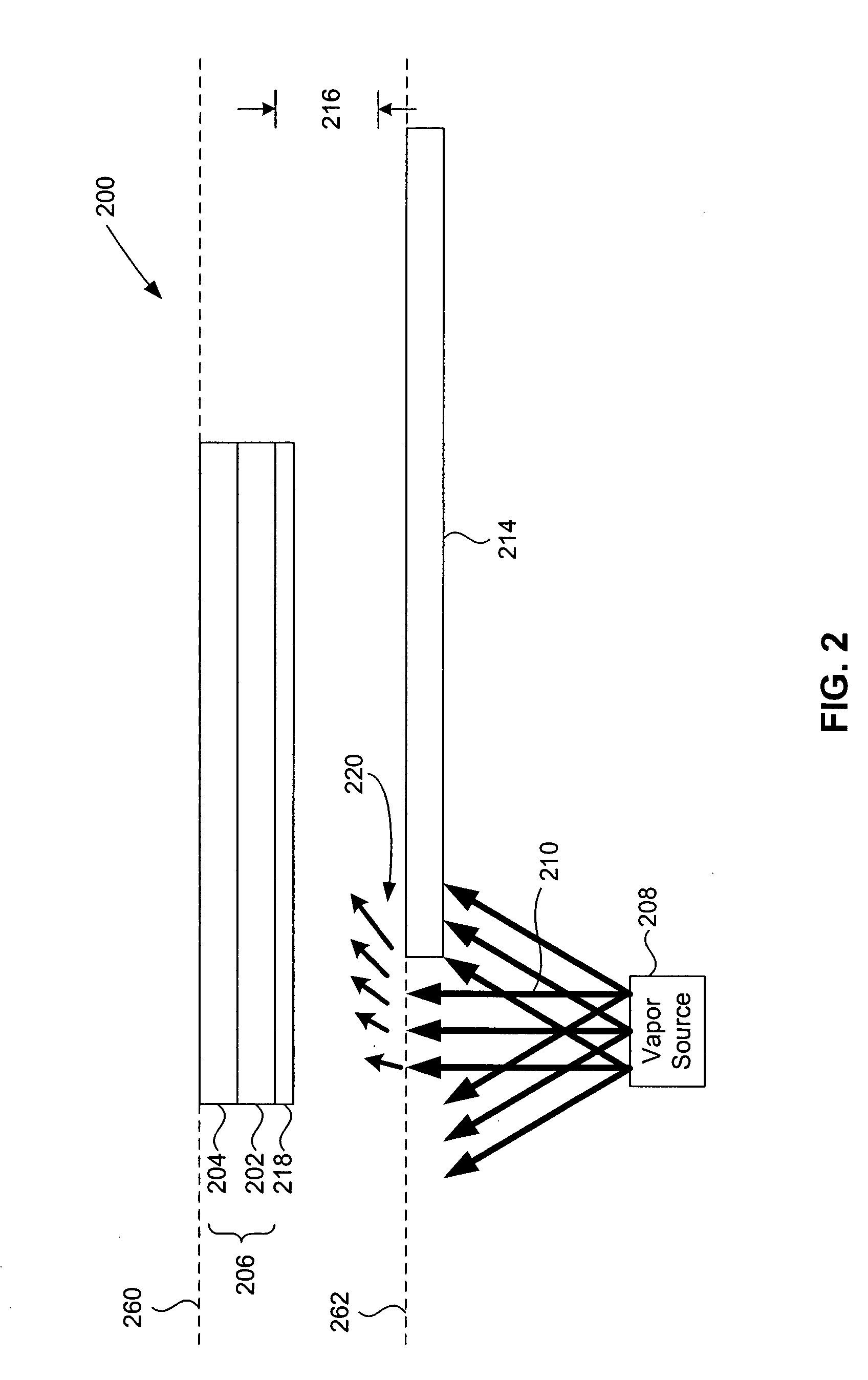
[0024] One or more embodiments of the present invention provide systems and methods to modify a layer on a pattern generator substrate used to form a pattern generator. This modification is done before the layer is diced to form a plurality of programmable patterning devices making up the pattern generator. The modification produces a reflected light beam pattern reflecting from the pattern generator having a trapeziodal shape at an image plane.

[0025]FIG. 4 shows a portion of a layer 450 of a substrate 452 having overlapping trapez...


PUM

PropertyMeasurementUnit
thicknessaaaaaaaaaa
thicknessaaaaaaaaaa
thicknessaaaaaaaaaa

Abstract

Systems and methods are used to modify a layer on a substrate that is used to form a pattern generator, so that light reflecting from the modified substrate has a trapezoidal or other custom profile. The layer is modified using various vapor deposition techniques in conjunction with moving or positioning the substrate a desired distance from a blocking device and / or at a desired rate or speed.

Description

BACKGROUND OF THE INVENTION [0001] 1. Field of the Invention [0002] The present invention is related to a lithography system. [0003] 2. Background Art [0004] Pattern generators are used to form patterned radiation images in many environments. For example, pattern generators can be used in televisions, biomedical patterning applications, lithography, and the like. [0005] When used in lithography systems, the pattern generators are used to pattern substrates during an exposure process. Example lithography systems include, but are not limited to, reflective or transmissive maskless, immersion, and mask-based photolithography. Example substrates include, but are not limited to, semiconductor wafers, flat panel display substrates, flexible substrates, and the like. Light interacting with an illumination spot on the pattern generator becomes patterned. The patterned light is projected using a projection optical system onto one or more target areas of the substrate during the exposure proc...

Claims


Application Information

Patent Timeline
Patent Type & Authority Applications(United States)
IPC IPC(8): C23C16/00
CPCC23C16/482G03F1/14G03F7/70291C23C16/042C23C14/044C23C14/24G03F7/70475G03F1/00G03F1/50
Inventor LIPSON, MATTHEWWILKLOW, RONALD A.
Owner ASML HLDG NV
Why Eureka
Try Eureka