Encapsulation of cells in biologic compatible scaffolds by coacervation of charged polymers

a cell and charged polymer technology, applied in the field of tissue engineering, can solve the problems of low initial cell number, low uniformity within the scaffold, and ineffective seeding, and achieve the effect of not being washed out of the scaffold so easily

Inactive Publication Date: 2006-01-26
AGENCY FOR SCI TECH & RES
View PDF4 Cites 44 Cited by
  • Summary
  • Abstract
  • Description
  • Claims
  • Application Information

AI Technical Summary

Benefits of technology

[0012] Using this method different attachment-dependent or attachment-independent cells can be encapsulated on the surface of a three dimensional scaffold to achieve a more effective seeding even with low initial cell numbers and a homogenous distribution of the cells within the scaffold. The cells are embedded in an ultra thin membrane formed by coacervation of the oppositely charged polymers to form a polymer complex. This polymer complex creates polymer fibers that form the basic structure of a polymer matrix in which the cells are embedded. Due to the ultra thin membrane cells are entrapped within the scaffold and cannot be washed out of the scaffolds so easily. As the cells are not attached directly to the surface of the scaffold but embedded in an ultra thin membrane that is attached to the scaffold, the method of the present invention is independent of the material and size of the scaffold used.

Problems solved by technology

However, conventional static seeding is not very efficient in delivery cells into scaffolds and often results in a very low initial cell number with low uniformity within the scaffold (Li et al., Biotechnol. Prog., 2001, Vol. 17, P.
However, the application of these methods are limited to scaffolds of a specific range of dimensions and pore sizes since most of the studies were performed on a single type of scaffold.
However, the extent of gelation (complexation) of such hydrogels cannot be controlled very well owing to the inherent variability in biological materials and there is no precise control over the physiochemical parameters that triggers the gelation of these biological hydrogels.
Sufficient gelation can effectively trap the cells inside the scaffolds but often limit the diffusion.
On the other hand, insufficient gelation will be good for mass transfer but not improving the cell seeding efficiency.

Method used


Image

  • Encapsulation of cells in biologic compatible scaffolds by coacervation of charged polymers
  • Encapsulation of cells in biologic compatible scaffolds by coacervation of charged polymers
  • Encapsulation of cells in biologic compatible scaffolds by coacervation of charged polymers

Examples


example 1

[0062] The following example describes the encapsulation of goat bone marrow stroma cells (BMSCs) into Cytomatrix™ scaffolds (Cytomatrix LLC, Woburn, Mass.) by the complex coacervation between modified collagen and terpolymer of hydroxylethyl methacrylate-methyl methacrylate-methyl acrylic acid (HEMA-MMA-MM).

[0063] In this example, the Cytomatrix™ scaffold is used as a three dimensional cell growth scaffold to assess the feasibility of encapsulating goat BMSCs by complex coacervation. The Cytomatrix™ scaffold is composed of biocompatible niobium-coated carbon with a thickness of about 3 mm and a diameter of about 9 mm. It has a regular, dodecahedral inner structure with continuous interconnected pores with a porosity of greater than 90%. Therefore, the Cytomatrix™ scaffold provides a microenvironment mimicking that of the bone marrow. Hence, the biomimetic three-dimensional microenvironment of the Cytomatri scaffold should be suitable for the proliferation of the goat BMSCs.

[0064]...

example 2

[0073] The following example describes the comparative experiments that are carried out to compare different methods of encapsulating cells in Cytomatrix™ scaffolds with charged polymers.

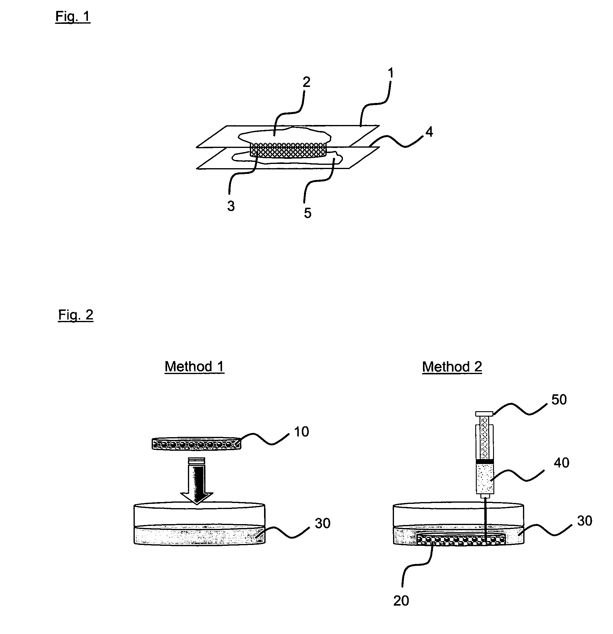
[0074] In this example, it is attempted to fill the three dimensional Cytomatrix scaffolds with 1.5 mg / ml of modified collagen and encapsulate the scaffold using 2.5% of terpolymer solution. Modified collagen and terpolymer solution are obtained as described in Example 1. In addition to the method of the present invention (FIG. 1), two further methods are used and described as follows (FIG. 2):

Method 1

[0075] 100 μl of 1.5 mg / ml of modified collagen is aliquoted into the Cytomatrix™ scaffold (10) and the scaffold is gently dipped into a reservoir of 2.5% terpolymer solution (30).

Method 2

[0076] The Cytomatrix™ scaffold (20) is first placed into a reservoir of 2.5% terpolymer solution (30). 1.5 mg / ml of modified collagen (40) is then delivered into the middle of the scaffold using a syringe with...

example 3

[0080] The following experiment describes the encapsulation of pig bone marrow stroma cells (BMSCs) into Cytomatrix™ scaffolds at different collagen-terpolymer contact times.

[0081] In this example, the density of the modified collagen-terpolymer complex is modulated by varying the contact time of the oppositely charged polymers used in the method of the present invention. The modified collagen and terpolymer as described in Example 1 are used.

[0082] For seeding pig BMSCs into scaffolds by encapsulation 1×10⁶ cells / ml of pig BMSCs are mixed with 1.5 mg / ml of modified collagen and 100 μl of the cell-collagen mixture is seeded into each scaffold as described in Example 1. Encapsulation of the cells in the scaffold is carried out as described in Example 1 using different contact time (1, 5, 10, 20 and 30 min). The scaffolds are then transferred into spinner flasks for dynamic culturing at 2 rpm for 2 weeks.

[0083] Controls are established by conventional static seeding. 1×10⁶ cells / ml...


PUM

PropertyMeasurementUnit
diameteraaaaaaaaaa
diameteraaaaaaaaaa
thicknessaaaaaaaaaa

Abstract

This invention relates to a method for the encapsulation of cells in biologic compatible three dimensional scaffolds and the use of such cells encapsulated in a scaffold. The cells are embedded in a charged polymer that is complex coacervating with an oppositely charged polymer within biologic compatible scaffolds. The polymer complex embedding the cells is forming an ultra thin membrane on the surface of the three dimensional scaffold.

Description

[0001] This invention relates to a method for the encapsulation of cells in biologic compatible scaffolds. The invention also relates to cell species encapsulated in such a scaffold, and uses of the cells encapsulated in such a scaffold. BACKGROUND OF THE INVENTION [0002] Scaffolds have been used extensively in the area of tissue engineering either to construct a neo-tissue that can be implanted to repair a defect site in the body or as a cell container in bioartificial devices. Scaffolds form a three dimensional matrix that serves as a template for cell proliferation and ultimately tissue formation. [0003] Culturing cells in a scaffold typically involves seeding cells throughout the scaffold and allowing the cells to proliferate in the scaffold for a pre-determined amount of time. A lot of research efforts have been directed at the design, fabrication and choice of materials in developing a scaffold for tissue engineering applications. However, the eventual success of a scaffold wi...

Claims


Application Information

Patent Timeline
Patent Type & Authority Applications(United States)
IPC IPC(8): C12N11/04C12N5/02
CPCA61L27/165A61L27/24A61L27/38A61L27/44A61L27/56A61L27/58C12N2533/30C12N5/0068C12N11/04C08L33/12
Inventor YU, HANRYTOH, YI CHIN
Owner AGENCY FOR SCI TECH & RES
Why Eureka
Try Eureka