
Method and apparatus of treating tissue

a tissue and apparatus technology, applied in the field of tissue treatment, can solve the problems of large diameter spots, high power (both electrical and light output) required to deliver permanent or long-lasting results, and high cost of treatments,

Inactive Publication Date: 2006-01-26
SHASER
View PDF99 Cites 178 Cited by
  • Summary
  • Abstract
  • Description
  • Claims
  • Application Information

AI Technical Summary

Benefits of technology

[0038]FIG. 18 is a graph of the reduction in laser powe...

Problems solved by technology

One disadvantage of the above described devices is that the power (both electrical and light output) required to deliver permanent or long lasting results are extremely high, and such devices are only suitable for use in a clinical setting with trained professionals operating the devices.
A further disadvantage is that the treatments are costly, painful, time consuming and only partially effective.
These newer devices which are capable of generating the “required” power level for effective long-term hair loss using a large diameter spots are large, heavy, expensive, require sophisticated cooling and are dangerous.
These are not devices that can be sold to individual consumers, or be operated safely in the home by average consumers.
Until now, little research has gone into understanding the actual behavior of light as it diffuses into tissue as it relates to the spot size.
As a result, the use of small spot treatments has been dismissed as not feasible in this area of dermatology.
The commonly held (though incorrect) understanding of how light diffuses into skin as a function of spot size has prevented the industry from developing effective methods for hair growth modulation for the end consumer.
The belief that only large diameter laser and IPL spots can cause hair loss has lead the entire industry to develop larger, more expensive and more dangerous devices; now producing more than 2900 W of output power.

Method used


Image

  • Method and apparatus of treating tissue
  • Method and apparatus of treating tissue
  • Method and apparatus of treating tissue

Examples


Embodiment Construction

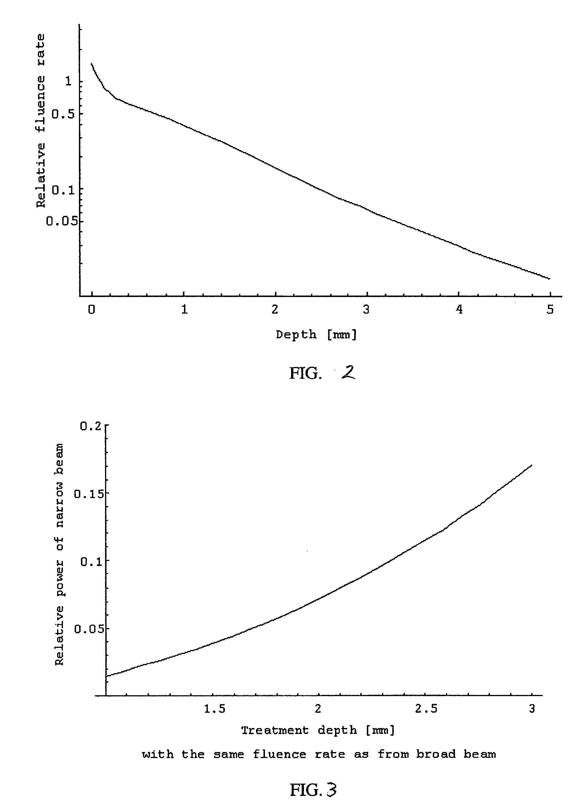
[0039] The theory of light diffusion in scattering media is used to determine the amount of fluence needed to have a cosmetic effect on the skin. In the near IR spectral region the absorption coefficient for skin is μa=0.02 mm−1. This coefficient gives the number of events of absorption for an average photon traveling along a 1-mm path. The reduced scattering coefficient for skin is μ′s=1.6 mm−1. This coefficient determines the number of events of photon isotropic scattering on the same path. Thus the possibility of a photon scattering is ˜2 orders of magnitude higher than for its absorption. That is why the light propagation in skin is described by diffusion equation rather than by regular wave theory.

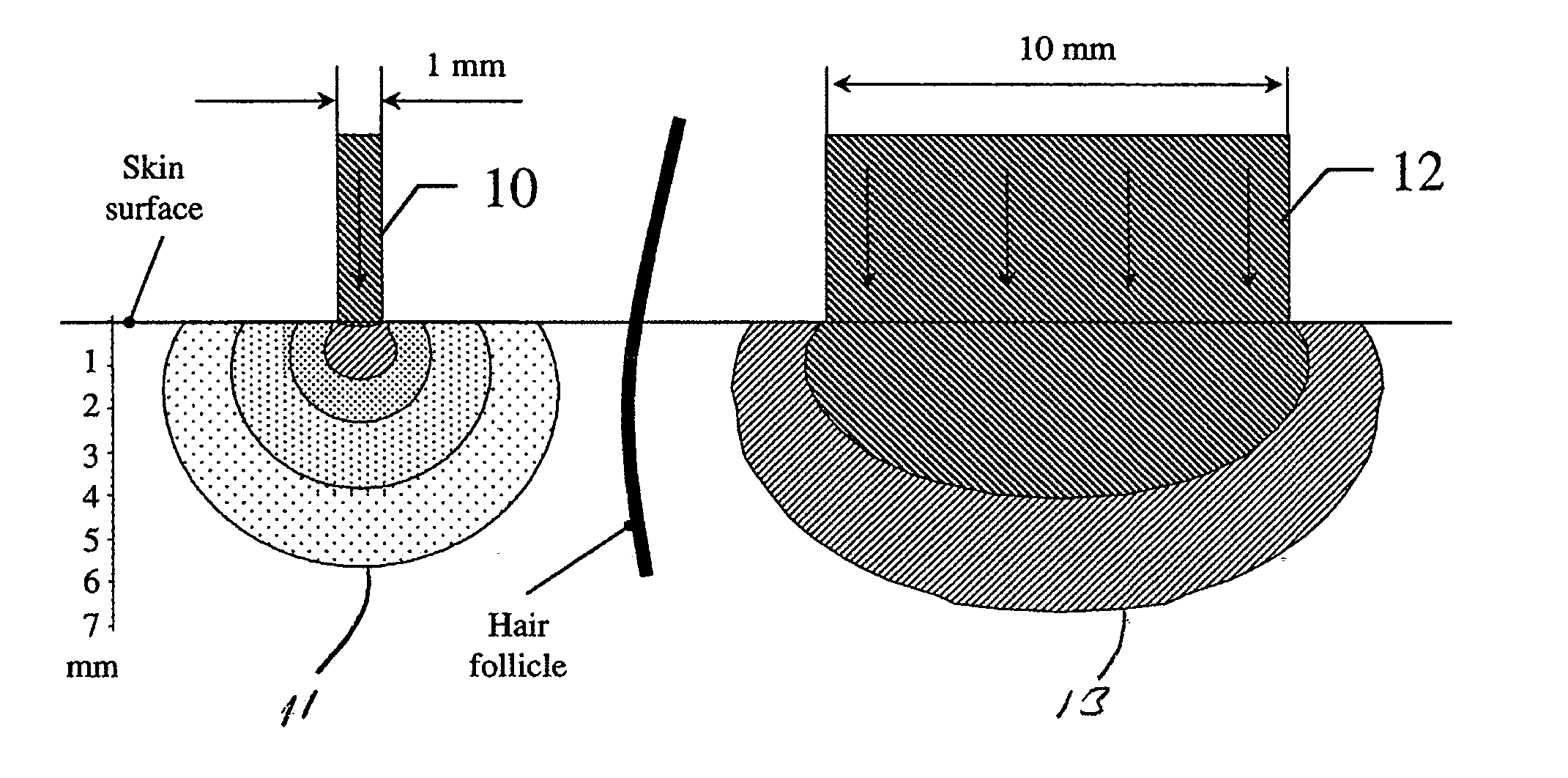
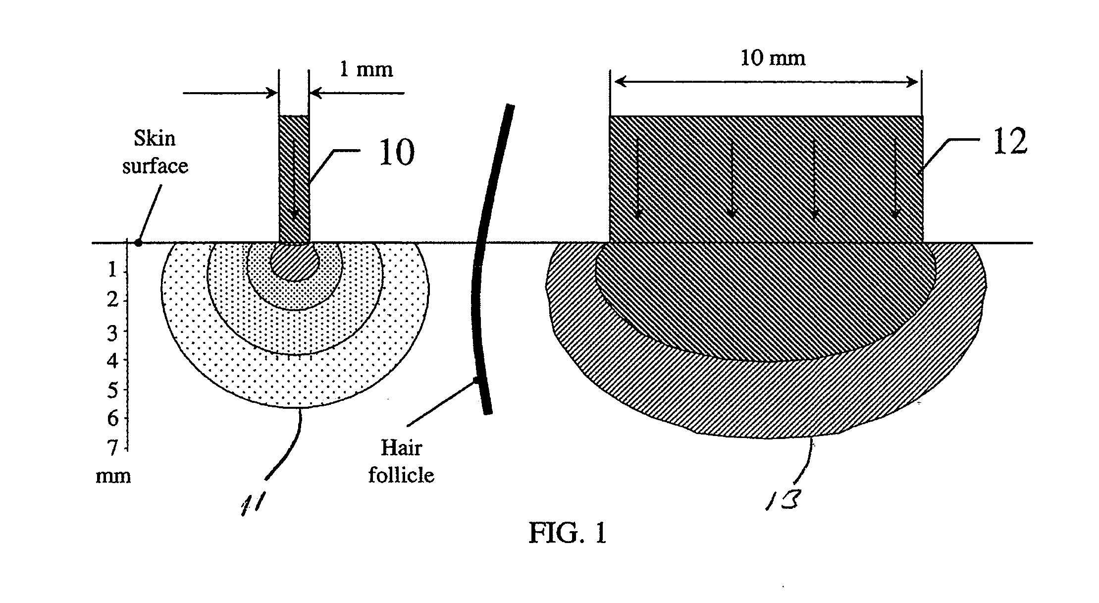
[0040] Referring to FIG. 1, two laser beams of equivalent power density or irradiance are seen in cross section penetrating a skin region with a hair follicle shown for scale. The first beam 10 is narrow and as a result its power will diffuse into the skin near to the surface forming...


PUM


Abstract

A method for the treatment of skin including the steps of determining the skin depth for energy absorption necessary for treatment; and generating a spot size for energy impinging on the skin to provide a desired amount of energy to the desired depth for treatment. In one embodiment the selected spot size has a small diameter. In another embodiment the spot diameter is narrower than the spacing between adjacent hairs on the skin. In another aspect the invention relates to an apparatus for the treatment of skin including a source of energy; and a means for selecting a spot size for energy from the source impinging on the skin to provide a desired amount of energy to a desired depth for treatment. In another embodiment the apparatus includes an interlock to prevent the laser from producing light unless the source is positioned to irradiate only the skin.

Description

CROSS-REFERENCE TO RELATED APPLICATION [0001] This application claims the benefit of and priority to U.S. provisional patent application Ser. No. 60 / 590,272 filed on Jul. 22, 2004, the disclosure of which is incorporated herein by reference in its entirety.FIELD OF THE INVENTION [0002] The invention relates generally to treating tissue and more specifically to dermatologic treatment using directed energy. BACKGROUND OF THE INVENTION [0003] Light has been used in a wide range of medical applications for many years. In the field of dermatology high powered lasers and intense pulsed light (IPL) systems have been used to permanently remove unwanted hair, rejuvenate skin, remove veins etc. In the field of hair removal, devices remove hair from areas of the body with large diameter pulses of laser or incoherent light called intense pulsed light. One disadvantage of the above described devices is that the power (both electrical and light output) required to deliver permanent or long lastin...

Claims


Application Information

Patent Timeline
IPC IPC(8): A61B18/20
CPCA61B18/203A61B2017/00752A61B2018/00452A61B2018/209A61B2018/00476A61B2018/1807A61B2018/2085A61B2018/0047A61B2018/20351A61B2018/20357A61B2018/20359A61B18/20A61B2018/208
Inventor DOVER, JEFFREY S.LAZAREV, VICTORROTH, DANIEL LAWRENCE
Owner SHASER
Learn More