Nonstented temporary valve for cardiovascular therapy
What is AI technical title?
AI technical title is built by Patsnap AI team. It summarizes the technical point description of the patent document.
a temporary valve and non-stent technology, applied in the field of medical methods and devices, can solve the problems of affecting the function of the valve, so as to achieve the effect of increasing the rigidity of the supporting component and enabling minimally invasive procedures on the valv
Active Publication Date: 2006-01-26
DIRECT FLOW MEDICAL INC
View PDF98 Cites 209 Cited by
Summary
Abstract
Description
Claims
Application Information
AI Technical Summary
This helps you quickly interpret patents by identifying the three key elements:
Problems solved by technology
Method used
Benefits of technology
Benefits of technology
[0024] Yet another embodiment of the present invention comprises a temporary heart valvecatheter, for enabling minimally invasive procedures on a valve in a beating heart. The catheter includes an elongate, flexible catheter body, having a proximal end and a distal end, a valve on the distal end, the valve comprising an inflatable structure; and at least one link between the catheter and the valve to prevent detachment of the valve from the catheter.
[0025] Another embodiment of the present invention comprises a method of in situ formation of a prosthetic valve support. A prosthetic valve is attached to a flexible support component which is incapable of retaining the valve at a functional site in the arterial vasculature. The support component extends both proximally and distally of the base of the valve. The valve is positioned at the site. The flexible support component is supplemented to increase the rigidity of the support component sufficiently to retain the valve at the site.
[0033] In accordance with a another embodiment of the present invention, there is provided a temporary heart valve catheter, for enabling minimally invasive procedures on a valve in a beating heart. The catheter comprises an elongate flexible catheter body, having a proximal end and a distal end. A valve is carried by the distal end. At least one link is provided between the catheter and the valve to prevent detachment of the valve from the catheter. The valve may be supported by a support frame, which is connected to a pull wire or wires extending axially throughout the length of the catheter. Axial tensioning of the pull wire relative to the catheter body deploys the valve into its functional configuration. Proximal retraction of the pull wire causes the valve to reduce in cross section and draw into the distal end of the catheter, such as for placement or removal. The link may comprise a connection between the pull wire and a valve support.
Patients with cardiac disease resulting in inability to carry on any physical activity without discomfort.
If any physical activity is undertaken, discomfort is increased.
Access to these sites generally include a thoracotomy or a sternotomy for the patient and include a great deal of recovery time.
Although valve repair and replacement can successfully treat many patients with valvular insufficiency, techniques currently in use are attended by significant morbidity and mortality.
Despite the many years of effort, and enormous investment of entrepreneurial talent and money, no stent based heart valvesystem has yet received regulatory approval, and a variety of difficulties remain.
For example, stent based systems have a fixed rigidity even in the collapsed configuration, and have inherent difficulties relating to partial deployment, temporary deployment, removal and navigation.
Method used
Image
Click on the blue label to locate the original text in one second.
Reading with bidirectional positioning of images and text.
Examples
Embodiment Construction
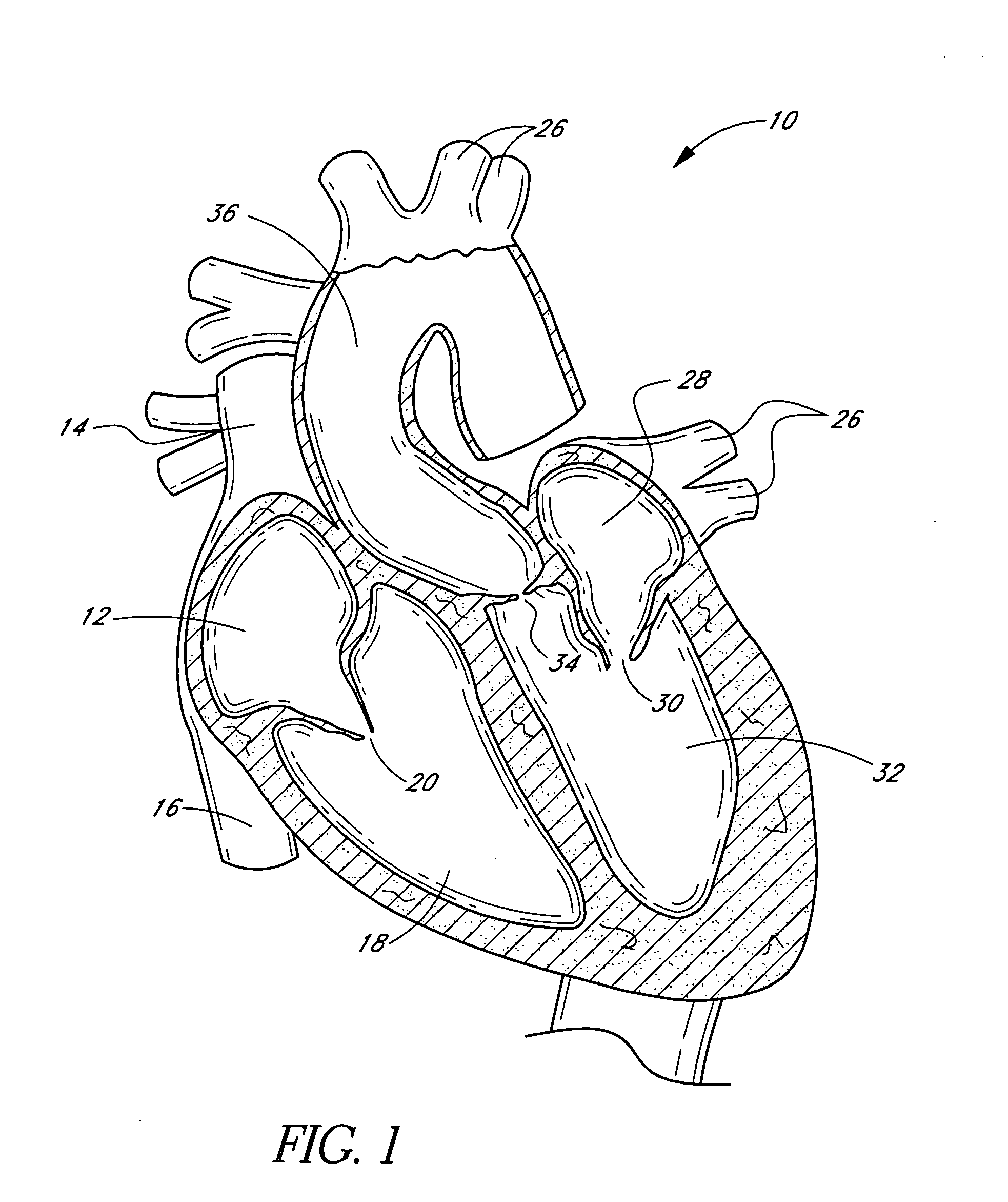
[0130]FIG. 1 is a schematic cross-sectional illustration of the anatomical structure and major blood vessels of a heart 10. Deoxygenated blood is delivered to the right atrium 12 of the heart 10 by the superior and inferior vena cava 14, 16. Blood in the right atrium 12 is allowed into the right ventricle 18 through the tricuspid valve 20. Once in the right ventricle 18, the heart 10 delivers this blood through the pulmonary valve 22 to the pulmonary arteries 24 and to the lungs for a gaseous exchange of oxygen. The circulatory pressures carry this blood back to the heart via the pulmonary veins 26 and into the left atrium 28. Filling of the left atrium 28 occurs as the mitral valve 30 opens allowing blood to be drawn into the left ventricle 32 for expulsion through the aortic valve 34 and on to the body extremities through the aorta 36. When the heart 10 fails to continuously produce normal flow and pressures, a disease commonly referred to as heart failure occurs.
[0131] One cause...
PUM
Abstract
A method of treating a patient utilizes a temporary valve. In one embodiment, an inflatable structure of a temporary valve is inflated at a cardiovascular site in fluid communication with a native valve. At least a portion of the native valve is removed translumenally. A prosthetic valve is deployed to compliment or replace a native valve. The temporary valve is removed.
Description
PRIORITY INFORMATION [0001] This application claims the priority benefit of (1) U.S. Provisional Application 60 / 568,402, filed May 5, 2004, (2) U.S. Provisional Application 60 / 572,561, filed May 19, 2004, (3) U.S. Provisional Application 60 / 581,664, filed Jun. 21, 2004, (4) U.S. Provisional Application 60 / 586,054, filed Jul. 7, 2004, (5) U.S. Provisional Application 60 / 586,110, filed Jul. 7, 2004, (6) U.S. Provisional Application 60 / 586,005, filed Jul. 7, 2004, (7) U.S. Provisional Application 60 / 586,002, filed Jul. 7, 2004, (8) U.S. Provisional Application 60 / 586,055, filed Jul. 7, 2004, (9) U.S. Provisional Application 60 / 586,006, filed Jul. 7, 2004, (10) U.S. Provisional Application 60 / 588,106, filed Jul. 15, 2004, (11) U.S. Provisional Application 60 / 603,324, filed Aug. 20, 2004, (12) U.S. Provisional Application 60 / 605,204, filed Aug. 27, 2004 and (13) U.S. Provisional Application 60 / 610,269 filed Sep. 16, 2004, the entire contents of which are hereby incorporated by reference ...
Claims
Application Information
Patent Timeline
Application Date:The date an application was filed.
Publication Date:The date a patent or application was officially published.
First Publication Date:The earliest publication date of a patent with the same application number.
Issue Date:Publication date of the patent grant document.
PCT Entry Date:The Entry date of PCT National Phase.
Estimated Expiry Date:The statutory expiry date of a patent right according to the Patent Law, and it is the longest term of protection that the patent right can achieve without the termination of the patent right due to other reasons(Term extension factor has been taken into account ).
Invalid Date:Actual expiry date is based on effective date or publication date of legal transaction data of invalid patent.

