
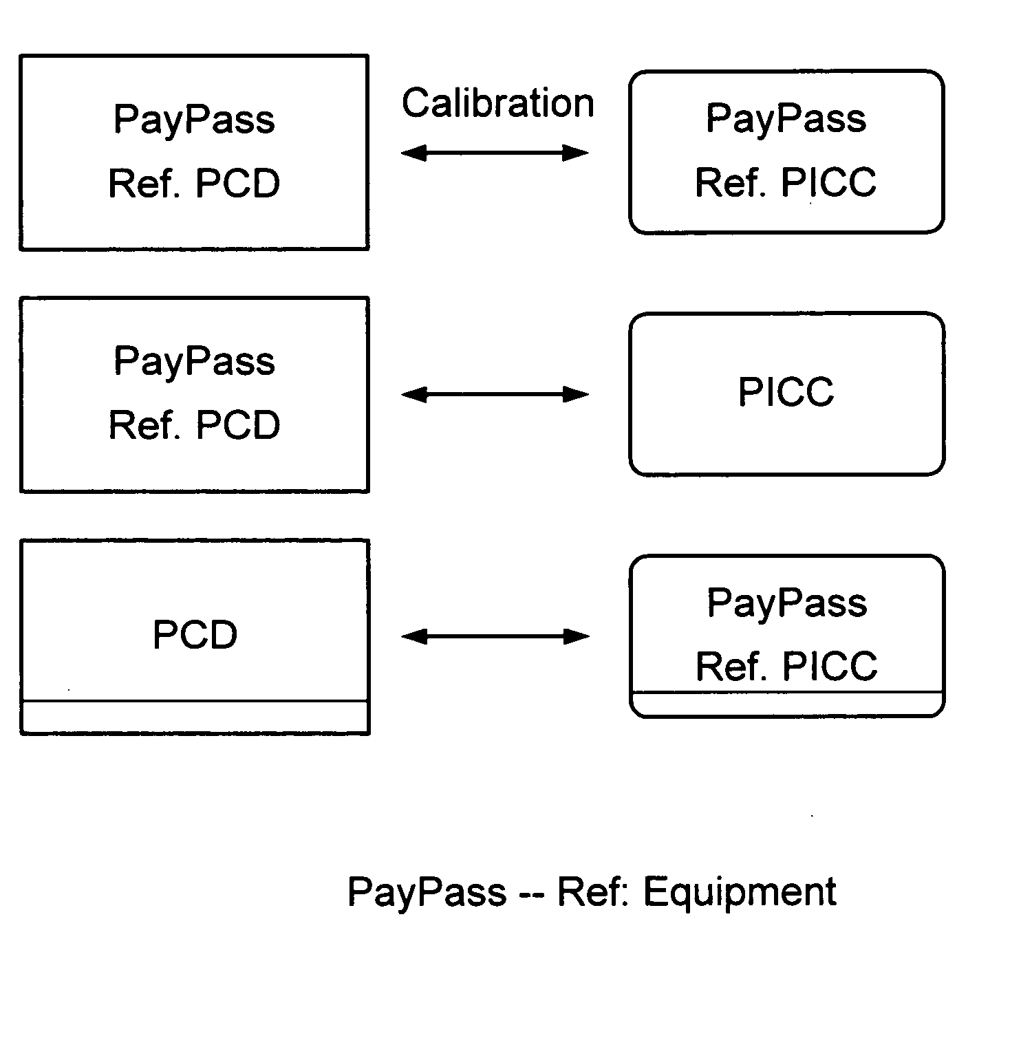
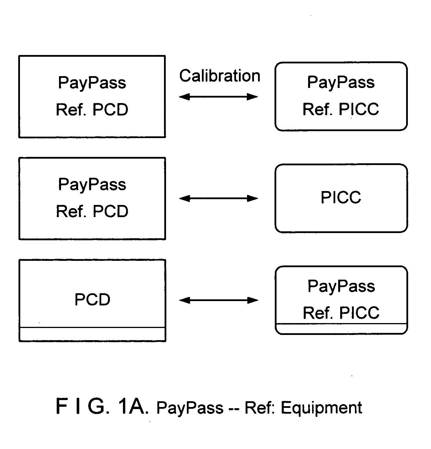
Reference equipment for testing contactless payment devices

Inactive Publication Date: 2006-02-02
MASTERCARD INT INC
View PDF21 Cites 19 Cited by
  • Summary
  • Abstract
  • Description
  • Claims
  • Application Information

AI Technical Summary

Benefits of technology

[0017] The reference equipment is designed to enhance interoperability of product payment devices whose functional behaviors may vary because of vendor customization of device specifications or due to manufacturing tolerances. In particular, the reference cards are designed to simulate or represent a full range of observed behaviors of product cards, which are issued to consumers. Similarly, the reference readers are designed to simulate or represent a full range of observed behaviors of product readers deployed in the field, for example, by merchants and stores. Specification compliance testing of product devices using these reference devices is likely to enhance interoperability of issued product cards with a product reader deployed in the field, and conversely of deployed product readers with a product card issued to a consumer.
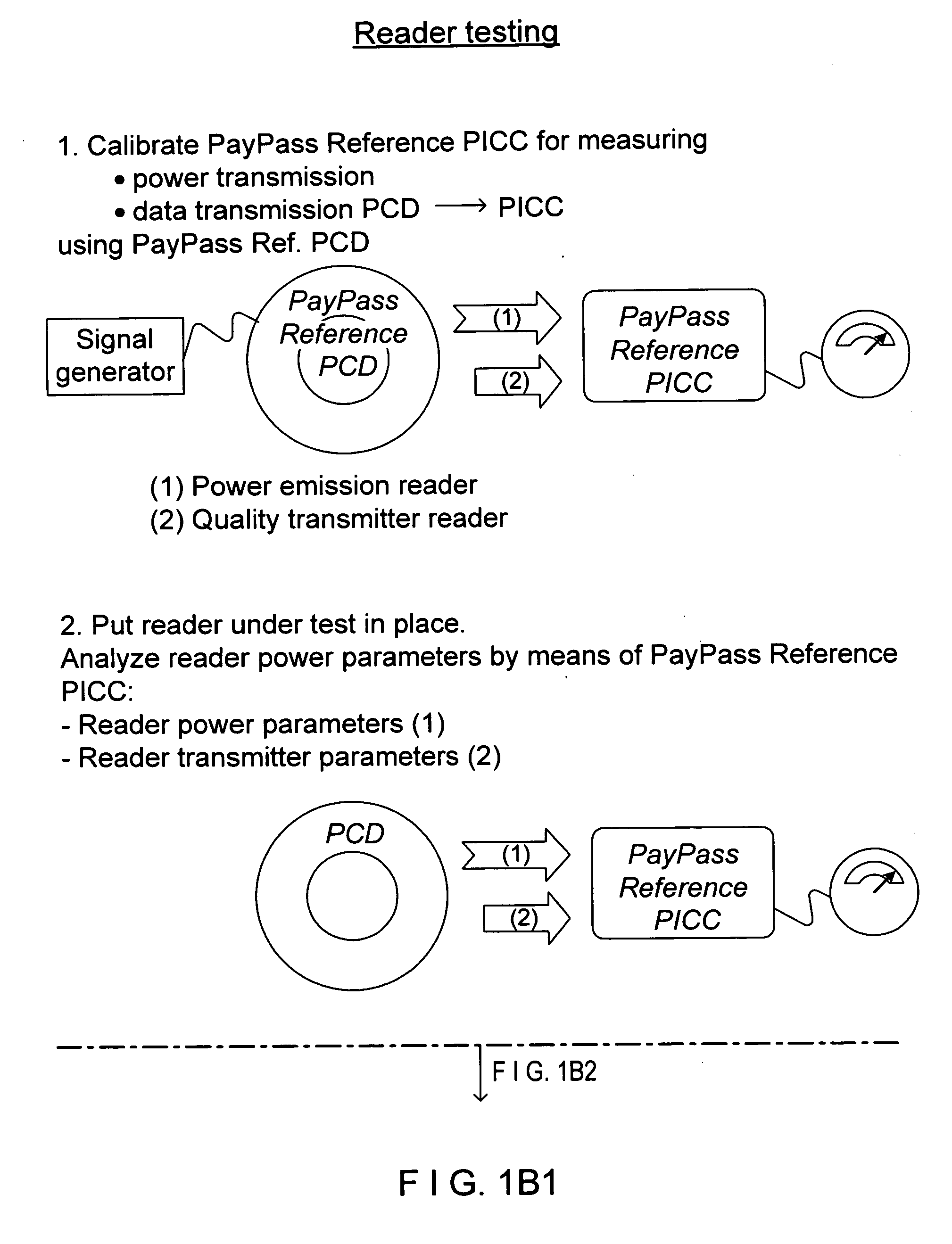
[0018] The reference devices may be used to establish acceptable specifications for issued cards and deployed readers using, for example, the methods disclosed in co-filed U.S. patent application Ser. No. ______. In the disclosed methods, the reference card and reference reader are cross-calibrated to link the operational specifications for the cards and the readers. A suitable selection of overlapping specification ranges or tolerances for proper card and reader functions, enhances the interoperability of the issued cards with a deployed reader, and conversely, the interoperability of deployed readers with an issued card.

Problems solved by technology

With existing card technology deployments, interoperability can be an issue.
Interoperability issues can arise even with card deployments that are presumably compliant with a single ISO standard (e.g., ISO 14443).
While the separate card and reader compliance test procedures under ISO 10373-6 may ensure that deployed product devices individually have characteristics that fall in either the designated specification range for cards or readers, the procedures do not ensure interoperability in the field.
This manner of standards compliance can lead to operational failure in the field.
For example, a marginally compliant card may be unreadable or difficult to read using a card reader that is also only marginally compliant.

Method used


Image

  • Reference equipment for testing contactless payment devices
  • Reference equipment for testing contactless payment devices
  • Reference equipment for testing contactless payment devices

Examples


Embodiment Construction

[0026] The present invention provides reference equipment for testing product payment devices that are deployed or used in the field for conducting electronic payment transactions. The reference equipment includes reference cards and reference card readers that respectively can be used to verify compliance of product cards and product readers with standard industry product specifications. The reference card and reader devices are designed so that their externally observable behavior is specified. The externally observable behavior is selected to replicate or simulate a nominal range of observed or expected behaviors of product devices deployed in the field. Using these reference devices to test product payment devices promotes interoperability of devices whose functional behaviors may vary due to vendor customization or due to manufacturing tolerances.

[0027] The inventive reference equipment is described herein in the context of implementations of electronic payment systems in whic...


PUM


Abstract

Reference equipment including a reference card and a reference reader is provided for testing electronic payment devices such as cards and card readers. The reference equipment is designed to simulate the external behavior of a variety of payment devices that are currently or expected to be deployed in electronic payment systems. Further, the reference equipment is configured to subject devices under test to extreme behaviors which are expected in field use or which are representative of a large class of payment devices. The external behaviors may relate to functional parameters, for example, power consumption, resonance frequency, Q-factor, modulation depth, noise, and timing. Exemplary reference devices are configured to exhibit representative external behavior, which is an empirically determined average behavior of the product devices in the field. Use of the reference equipment for product specification compliance testing will enhance the interoperability of product payment devices.

Description

CROSS-REFERENCE TO RELATED APPLICATIONS [0001] This application claims the benefit of U.S. provisional patent application No. 60 / 588,270 filed on Jul. 15, 2004. This application is also related to United States patent applications Ser. No. ______, and Ser. No. ______, Ser. No. ______, and Ser. No. ______, co-filed on even date, all of which claim the benefit of the aforementioned patent application No. 60 / 588,270. All of the aforementioned patent applications are hereby incorporated by reference herein in their entiretiesBACKGROUND OF THE INVENTION [0002] Radio Frequency Identification (RFID) tags are small integrated circuits (ICs) connected to an antenna, which can respond to an interrogating RF signal with simple identifying information, or with more complex signals depending on the size of the IC. RFID technology does not require contact or line of sight for communication. Radio Frequency Identification (RFID) technology is now economically viable and is deployed in more and mor...

Claims


Application Information

Patent Timeline
IPC IPC(8): G06K7/08G06K19/06G06Q20/32G06Q20/34
CPCG01R31/302G01R31/308G06K7/00G06K7/0008G06K7/0095G06K7/10019G07F7/1008G06K7/10465G06K17/00G06Q20/32G06Q20/327G06Q20/341G07F7/084G06K7/10336H04B5/48
Inventor SMETS, PATRICKVAN DE VELDE, EDDY LODEWIJK HORTENSIAGARRETT, DUNCAN
Owner MASTERCARD INT INC
Learn More