Laser-GPS marking and targeting system

a laser-gps and targeting system technology, applied in the direction of distance measurement, instruments, using reradiation, etc., can solve problems such as errors, and achieve the effect of increasing the efficiency of existing laser marking and targeting systems

Inactive Publication Date: 2006-02-02
FILEP ZOLTAN
View PDF7 Cites 25 Cited by
  • Summary
  • Abstract
  • Description
  • Claims
  • Application Information

AI Technical Summary

Benefits of technology

[0008] The invention is directed to increase the efficiency of existing laser marking and targeting systems, helping also decision making and process control.

Problems solved by technology

All these information, not being in a compact package, are hard to process, giving the possibility for errors to occure.

Method used


Image

  • Laser-GPS marking and targeting system
  • Laser-GPS marking and targeting system
  • Laser-GPS marking and targeting system

Examples


Embodiment Construction

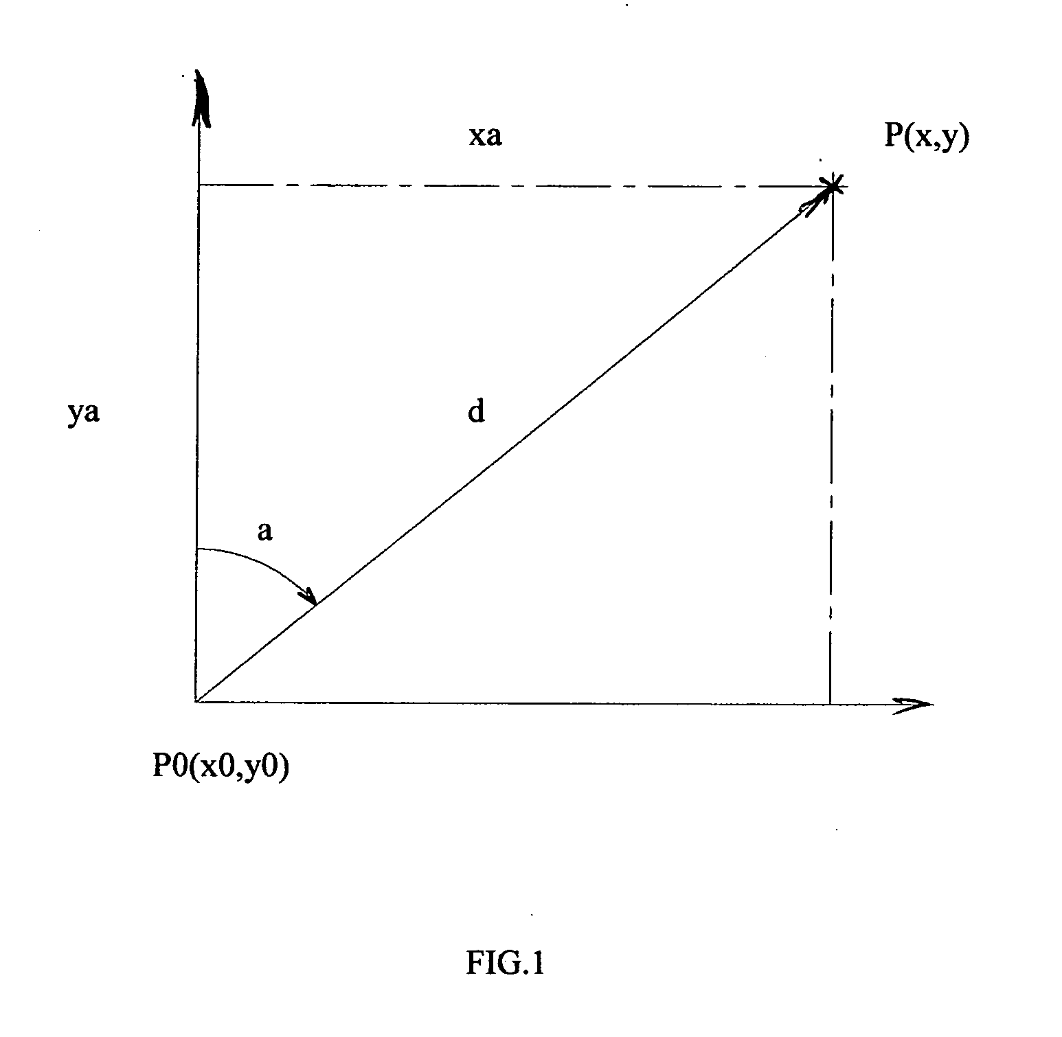
[0017]FIG. 1 is a general view of the relation between the observer / origin P0(x0,y0) and the target object P(x,y).

xa and ya—are horizontal and vertical components of the distance d from the origin to the target.

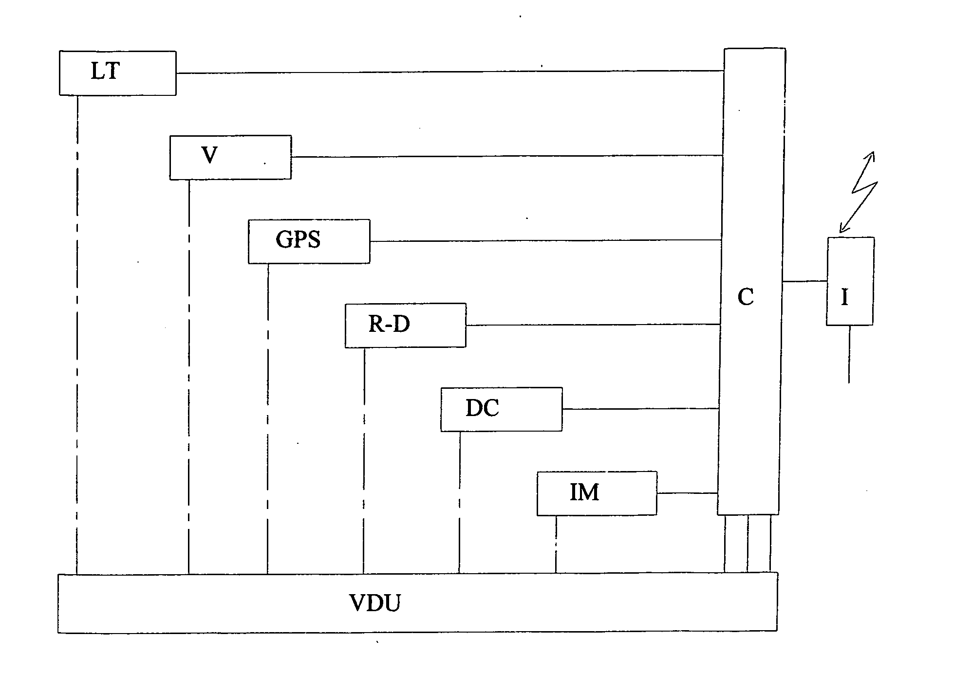
[0018] The value of the distance d is given by the laser range finder or any other distance reading equipment / module.

a—is the angular direction towards North, value given by a digital compass, by example.

[0019] This way, we have the values:

Xa=d*sin a

Ya=d*cos a

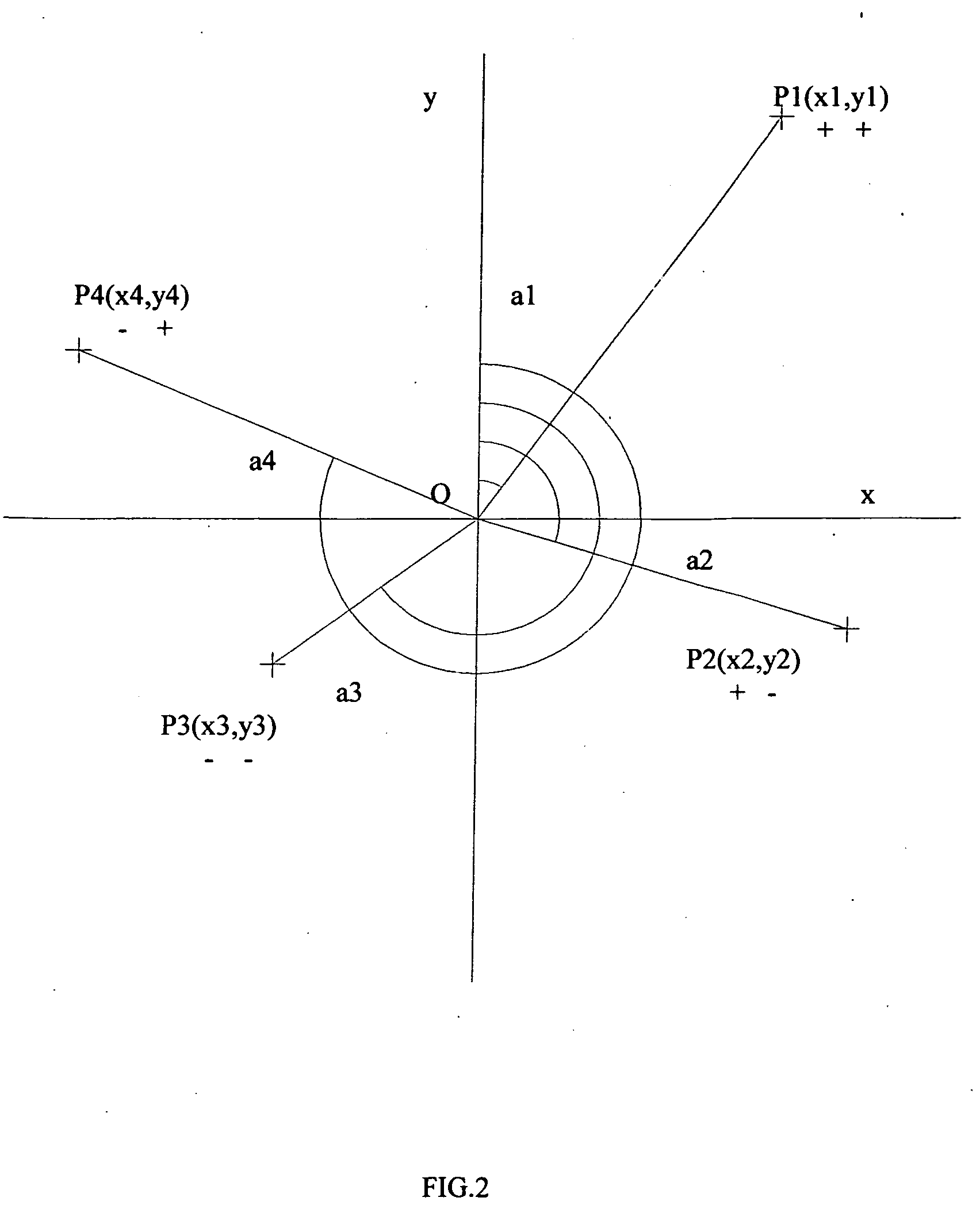
[0020] We can observe from FIG. 2, that the sign of the x and y coordinates is following the sign of the sin a and cos a functions, thru the 4 quadrants.

[0021] Making 2 consecutive readings, like in FIG. 3, we can determine motion vector parameters of the target, or we can simply forward the readings to the central processing unit.

[0022] The resulting global distance values are:

for the northern hemisphere

x=x0+xa=x0+d*sin a

y=y0+ya=y0+d*cos a

for the southern hemisphere

x=x0+xa=x0+d*sin a

y=y0−ya=y0−d*cos a...


PUM


Abstract

What is new in this invention, it is the complete automation of coordinate data collection of remote target objects. It is also a new procedure a single measurement instead of multiple triangulation measurements for coordinate data collection.

Description

[0001] A combined method is provided for non invasive and non contact laser and / or GPS marking for processing of targeted objects. [0002] The target object viewing, selection, marking, together with information acquisition, processing and transmission is done by the equipment. BACKGROUND OF THE INVENTION [0003] Observation and marking is an important component in the processing of objects. The GPS coordinates and other additional information are essential in modem fire management. [0004] Existing equipment and systems are giving bits of information about a target. All these information, not being in a compact package, are hard to process, giving the possibility for errors to occure. [0005] It is useful and even necessary to have a clear, possibly computerized collection and processing of as much information as possible. [0006] This information has to be collected and packed from the field and transmitted to the fire management or other process control unit. [0007] A higher level of ...

Claims


Application Information

Patent Timeline
Patent Type & Authority Applications(United States)
IPC IPC(8): G01C1/00G01C3/08G01B11/26G01S1/00G01S19/35
CPCF41G3/02F41G3/06G01S19/51G01C21/20G01S17/023G01C15/00G01S17/86
Inventor FILEP, ZOLTAN
Owner FILEP ZOLTAN
Why Eureka
Try Eureka