[0008] The invention aims to provide a hydrodynamic bearing device in which the bearing performance is satisfactorily maintained in a
stable state over a long period of time by circulating the operating fluid through the hydrodynamic bearing and efficiently removing the air bubbles in the operating fluid during the operation of the hydrodynamic bearing device without the operating fluid leaking outward or involving sudden fluctuation.
[0010] In the above configuration, even when one of the shaft and the sleeve is relatively rotated causing the operating fluid to circulate and flow through the inner part of the sleeve and the space between the sleeve and the cover and the air bubbles to attach to the
dynamic pressure generating grooves and the like of the radial hydrodynamic bearing, the air bubbles break away from the
dynamic pressure generating groove and circulate by the circulation flow, and when flowing into the fluid storage space from the communicating path through the introducing minimum clearance, the air bubbles are separated from the operating fluid and exhausted through the vent hole. Thus, lowering of bearing function such as, lowering of
bearing stiffness due to air bubbles and
instability of rotation during rotating operation is prevented.
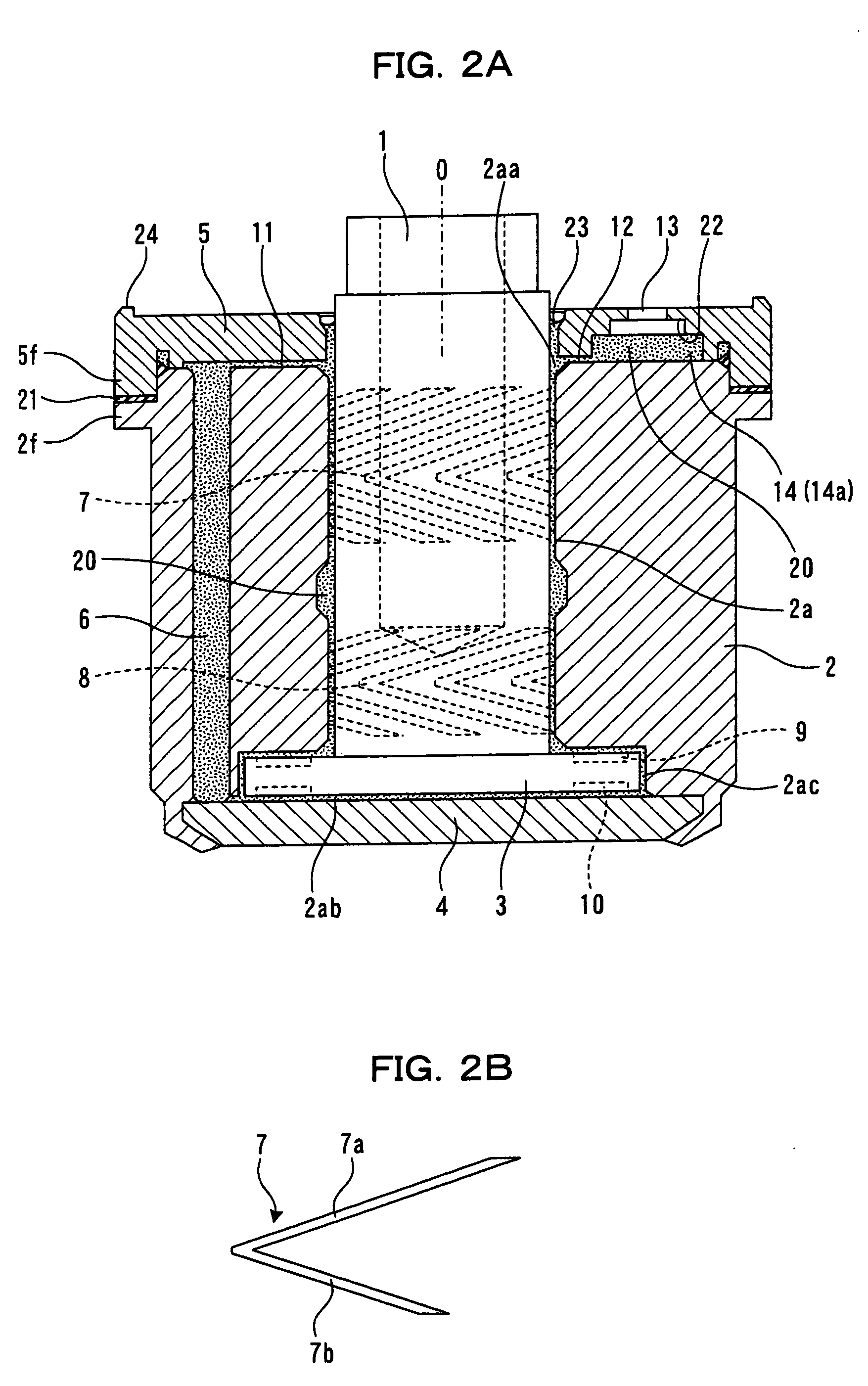
[0011] One aspect of the invention is that the fluid storage space is formed into a shape that inclines with respect to the circumferential direction so that a separating distance from the end face on the open end of the sleeve becomes larger from the introducing minimum clearance toward the vent hole side. According to such configuration, even when the hydrodynamic bearing device is subjected to an external
impact or the orientation is suddenly changed, the interface between the air and the operating fluid in the fluid storage space remains in the proximity of the vent hole and is prevented from moving in the circumferential direction. Thus, leaking of the operating fluid to the outside involved in the movement of the air bubbles can be prevented. Further, at the location in the proximity of the vent hole, the interface has a shape that changes in the circumferential direction, and thus fluctuation of the area of the interface or the
surface tension involved therewith is small.
[0013] A still further aspect of the invention is that an operating fluid storing part for storing the operating fluid in communication with the outside air is formed on the inner
peripheral surface facing the shaft of the cover, the operating fluid storing part including an inclined surface that inclines so that an inner
diameter of the cover becomes larger as the distance from the end face on the open end of the sleeve becomes larger, and the inner
diameter of the operating fluid storing part is formed into a shape in which a
surface tension of the operating fluid stored in the operating fluid storing part and a
surface tension of the operating fluid facing the vent hole are substantially balanced. According to such configuration, a sudden change in the position of the interface and the leakage of the operating fluid caused by such change in interface can be prevented.
[0014] Another aspect of the invention is that an operating fluid storing part for storing the operating fluid in communication with the outside air is formed on the outer
peripheral surface of the shaft facing the inner
peripheral surface of the cover, the operating fluid storing part including an inclined surface that inclines so that an outer diameter of the shaft becomes smaller as the distance from the end face on the open end side of the sleeve becomes larger, and the operating fluid storing part is formed into a shape in which a surface tension of the operating fluid stored in the operating fluid storing part and a surface tension of the operating fluid facing the vent hole are substantially balanced. According to such configuration, in addition to the sealing effect by the surface tension in a
stationary state, a sealing effect by a
centrifugal force generated through shaft rotation during the operation is also provided, thereby preventing a sudden change in the position of the interface and the leakage of the operating fluid caused by such change in interface.
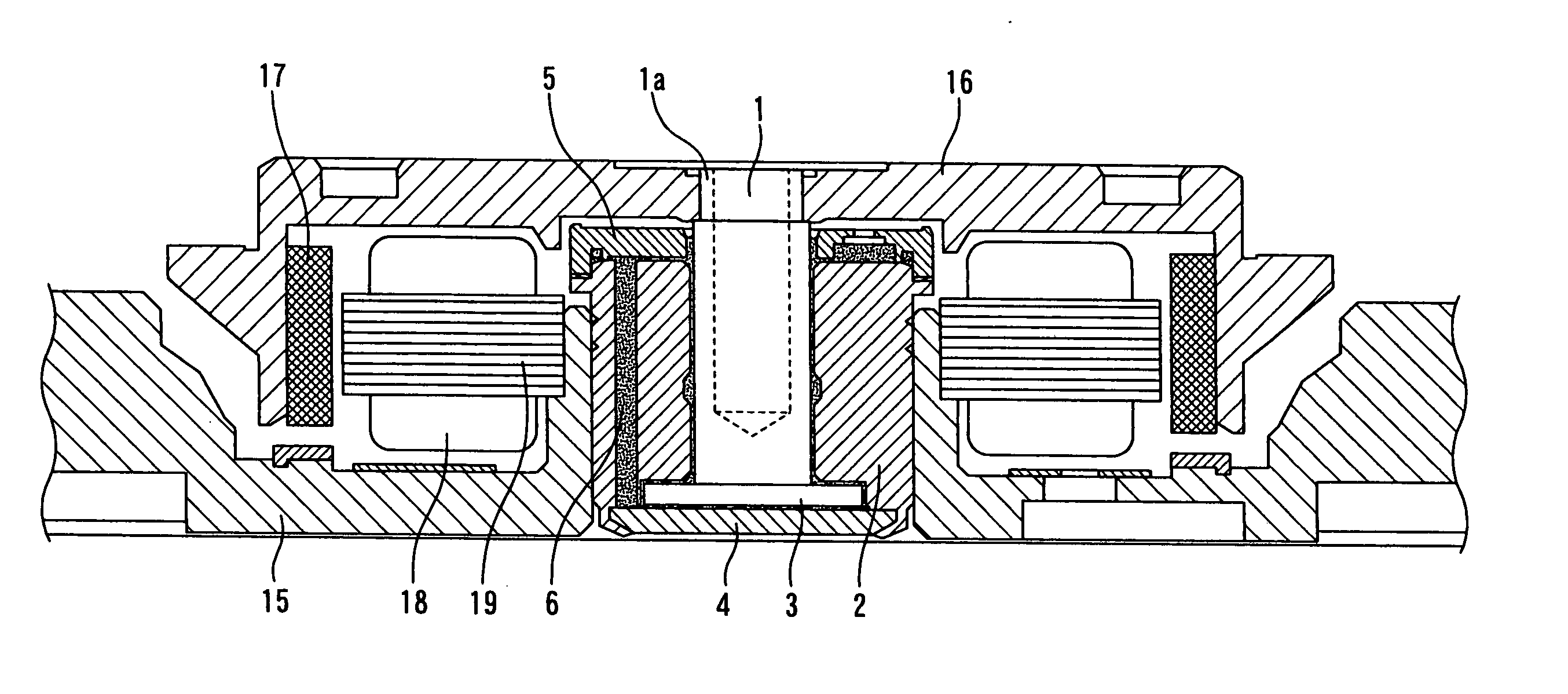
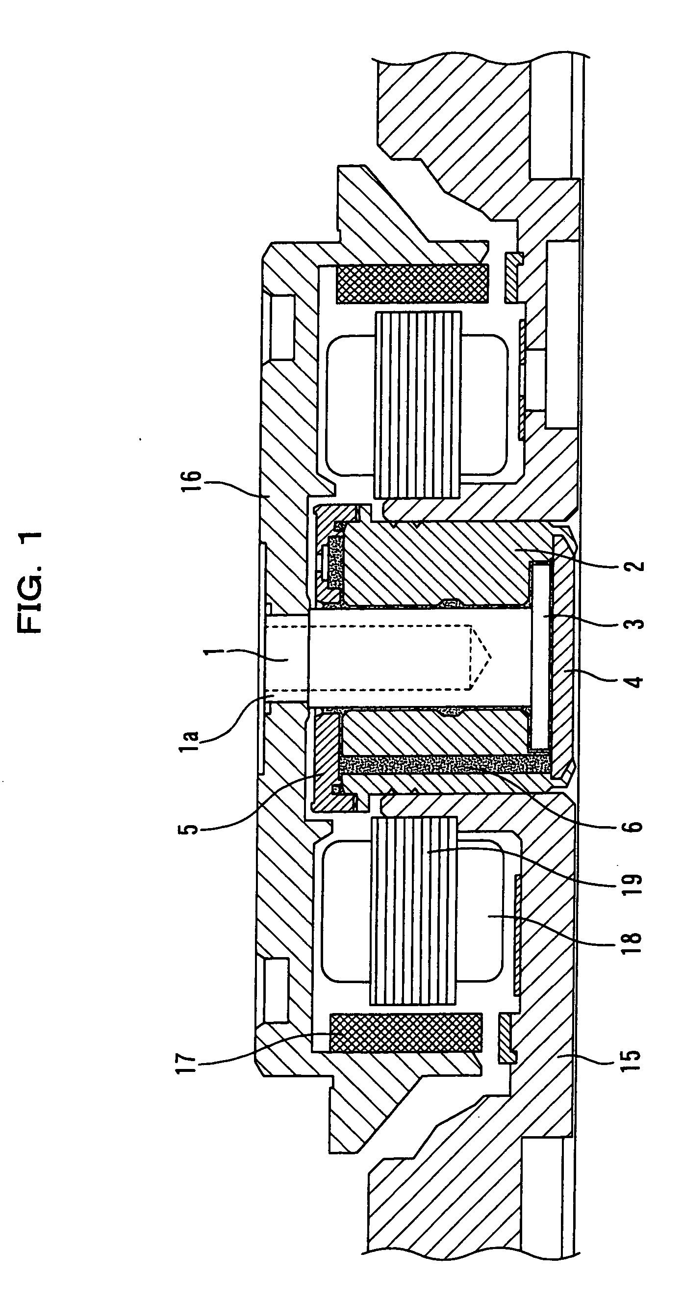
[0019] According to the hydrodynamic bearing device of the invention, during the rotating operation of the shaft, the operating fluid in the
dynamic pressure generating groove of the radial hydrodynamic bearing flows toward the dynamic pressure generating groove of the thrust hydrodynamic bearing, passes through the communicating path, through a narrow clearance formed between the end face on the open end of the sleeve and the cover by the capillary phenomenon, and flows back to the dynamic pressure generating groove of the radial hydrodynamic bearing. When the operating fluid flows back, the air contained as air bubbles is separated from the fluid in a fluid storage space that is also formed between the end face on the open end side of the sleeve and the cover and that is greater than the clearance, and only the air is released outside from the vent hole. Thus, the air in the operating fluid is gradually removed. Since the operating fluid does not leak out from the vent hole, the HDD device can be prevented from being polluted. Particularly, since the fluid storage space is formed into a shape that inclines with respect to the circumferential direction so that the separating distance from the end face on the open end of the sleeve becomes larger from the introducing minimum clearance toward the vent hole, even when the hydrodynamic bearing device is subjected to an external
impact or the orientation thereof is suddenly changed, the leakage of the operating fluid to the outside involved in the movement of the air bubbles can be prevented. Therefore, lowering of bearing function such as, lowering of
bearing stiffness due to air bubbles and
instability of the rotation during rotating operation can be prevented, and further, the operating fluid can be reliably prevented from leaking outward and thus reliability can be enhanced.

