
Bearing apparatus for a driving wheel of vehicle

Inactive Publication Date: 2006-02-02
NTN CORP
View PDF0 Cites 19 Cited by
  • Summary
  • Abstract
  • Description
  • Claims
  • Application Information

AI Technical Summary

Benefits of technology

[0011] It is an object of the present invention to provide a vehicle bearing apparatus for a driving wheel which reduces generation of stick-slip noise as well as fretting wear and thus improves durability of the bearing apparatus.
[0013] Since the end surfaces of the shoulder of the outer joint member inserted into the inner member abut one another and the end surface of the inner member is previously formed so that these end surfaces line contact with each other at a vertex formed by inclined surfaces on the end of the inner, these end surfaces can surface contact each other. This is because the end surface of the shoulder is inclined due to extension of the shaft portion of the outer joint member when the inner member and the outer joint member are joined together by fastening the nut. Thus, it is possible to provide a bearing apparatus for a vehicle driving wheel which can reduce and maybe prevent generation of stick-slip noise as well as fretting wear and thus improve durability of the bearing apparatus.
[0014] According to the present invention, the inner member comprises a wheel hub with a wheel mounting flange. An inner raceway surface is formed on the outer circumferential surface of the wheel hub. One inner raceway surface opposes one of the outer raceway surfaces. The wheel hub also includes a cylindrical portion axially extending from the inner raceway surface. An inner ring is press fit onto the axially extending cylindrical portion of the wheel hub. The ring has an inner raceway surface formed on the outer circumferential surface. The other inner raceway surface opposes the other outer raceway surface. The inner ring is axially immovably secured relative to the wheel hub by a caulked portion formed by radially outwardly plastically deforming the end of the axially extending cylindrical portion. The inner end surface of the caulked portion abuts the end surface of the shoulder of the outer joint member. The end surface of the shoulder of the outer joint member and the end surface of the inner member surface contact each other. This is because that the end surface of the shoulder is inclined due to extension of the shaft portion of the outer joint member when the inner member and the outer joint member are joined together by fastening the nut. Thus, it is possible to reduce the bearing stress applied to the caulked portion and to provide a bearing apparatus for a vehicle driving wheel which can reduce or prevent generation of stick-slip noise as well as fretting wear and thus can improve durability of the bearing apparatus.
[0016] According to the present invention, an axially deformable length between the end surface of the shoulder and the end surface of the inner member is set within a range of 0.010˜0.015 mm. This makes it possible to effectively achieve the surface contact between the abutting surfaces of the inner member and the shoulder of the outer joint member. This is due to the fact that the end surface of the shoulder is inclined due to extension of the shaft portion of the outer joint member when the inner member and the outer joint member are joined together by fastening the nut
[0017] The bearing apparatus for a vehicle driving wheel comprises an outer member formed with double row outer raceway surfaces on its inner circumferential surface. An inner member is formed with double row inner raceway surfaces arranged opposite to the double row outer raceway surfaces. Double row rolling elements are freely rollably contained between the outer and inner raceway surfaces, respectively, of the outer and inner member. A constant velocity universal joint, for torque transmission, is inserted into the inner member. The constant velocity universal joint abuts and is axially separably connected via a nut. The end surface of a shoulder of an outer joint member and the end surface of the inner member are previously formed so that these end surfaces line contact with each other at a vertex formed by inclined surfaces on the end of the inner member. Accordingly, the end surface of the shoulder of the outer joint member and the end surface of the inner member can surface contact each other. Thus, it is possible to provide a bearing apparatus for a vehicle driving wheel which can reduce or prevent generation of stick-slip noise as well as fretting wear and thus improve durability of the bearing apparatus.

Problems solved by technology

However, in the bearing apparatus of the prior art, a problem exists in that the end surface of the shoulder 60 is inclined due to extension of the shaft portion 61 of the outer joint member 62 when the wheel hub 51 and the outer joint member 62 are joined together by the nut 66.
This causes repeating relative rotation between the caulked portion 51c and the shoulder 60 over a long term and thus cause not only stick-slip noise but rattle due to progression of fretting wear.

Method used


Image

  • Bearing apparatus for a driving wheel of vehicle
  • Bearing apparatus for a driving wheel of vehicle
  • Bearing apparatus for a driving wheel of vehicle

Examples


Embodiment Construction

[0028] The following description of the preferred embodiment(s) is merely exemplary in nature and is in no way intended to limit the invention, its application, or uses.

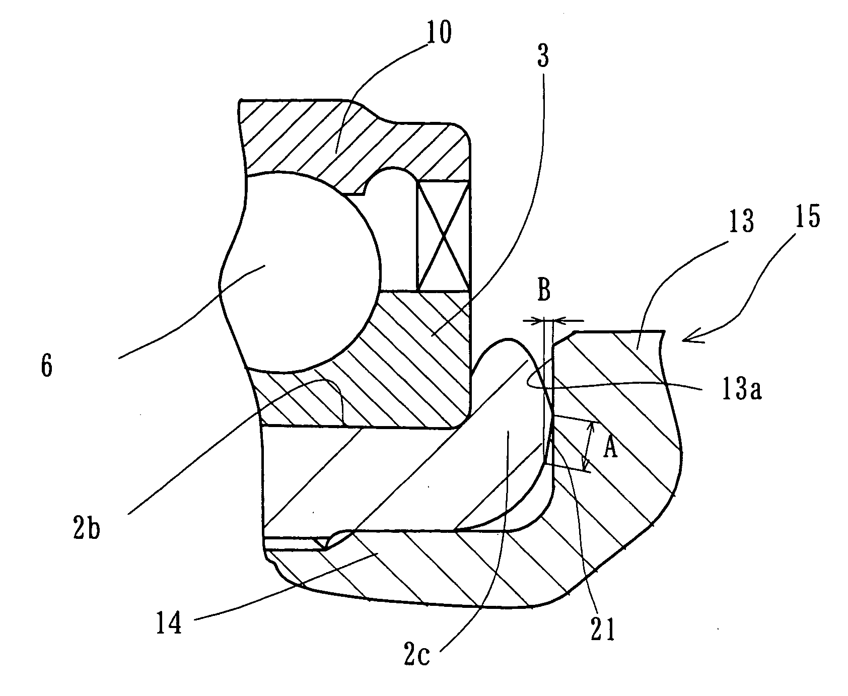
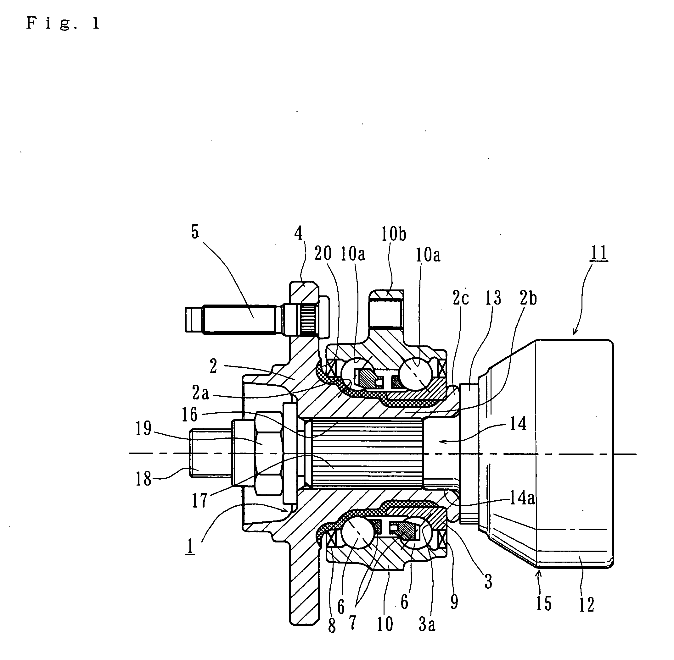
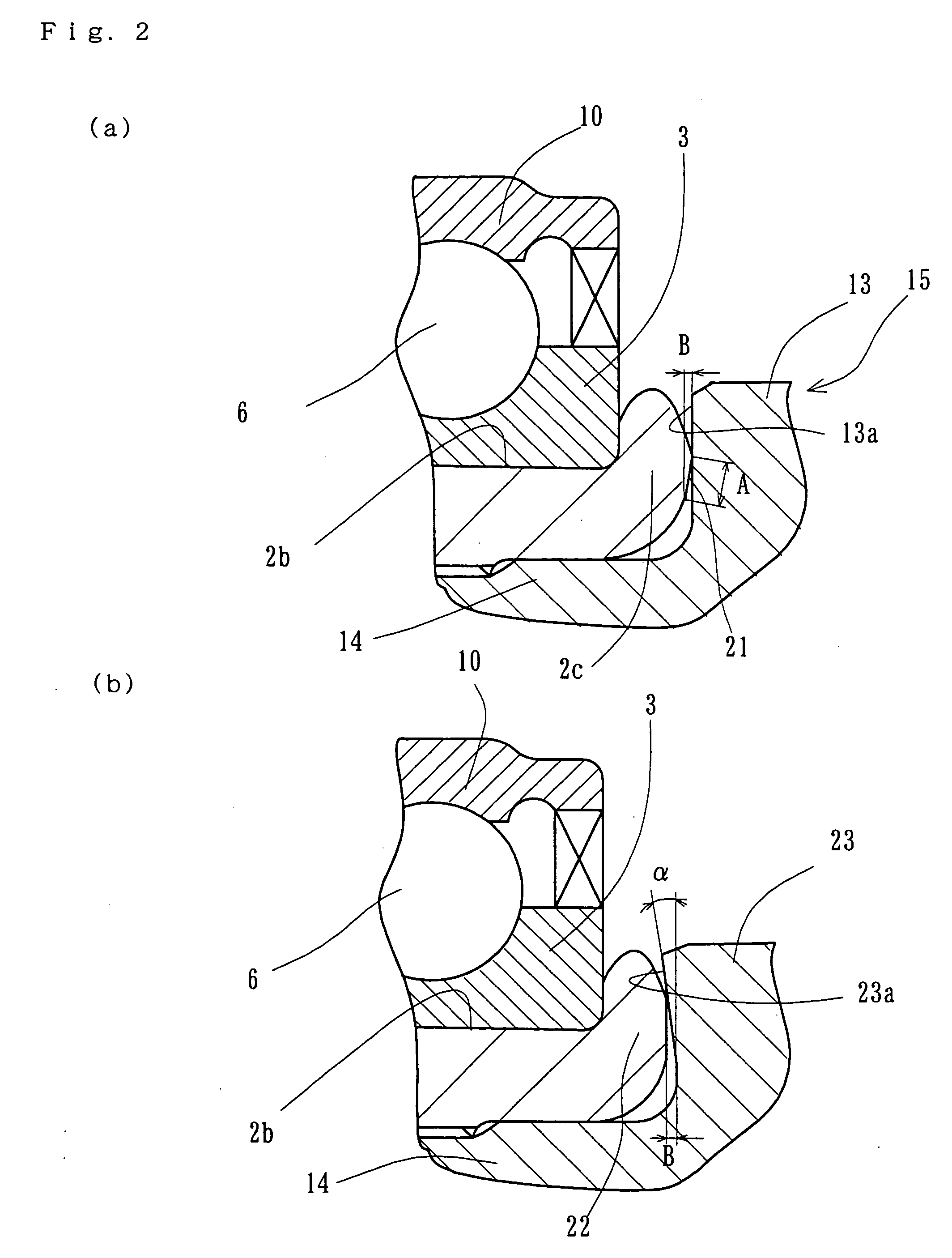
[0029]FIG. 1 illustrates a first embodiment of a bearing apparatus for a vehicle driving wheel of the present invention, FIG. 2 (a) is an enlarged view of a portion of FIG. 1, and FIG. 2 (b) is an enlarged view showing a modification of FIG. 2 (a). In the description below, the term “outboard side” (a left-hand side in drawings) of the apparatus denotes a side which is positioned outside of the vehicle body. The term “inboard side” (a right-hand side in drawings) of the apparatus denotes a side which is positioned inside of the body when the bearing apparatus is mounted on the vehicle body.

[0030] The vehicle driving wheel bearing apparatus includes an inner member 1, an outer member 10, and a double row rolling elements (balls) 6 rollably contained between the inner and outer members 1 and 10. The inner member 1 in...


PUM


Abstract

A bearing apparatus for a vehicle driving wheel which prevents generation of stick-slip noise as well as fretting wear to improve durability of the bearing apparatus has an outer member (10) formed with double row outer raceway surfaces (10a, 10a) on its inner circumferential surface. An inner member (1, 27) is formed with double row inner raceway surface (2a (24a), 3a) opposite to the double row outer raceway surfaces (10a, 10a). Double row rolling elements (6) are freely rollably maintained between the outer and inner raceway surfaces (10a, 10a; 2a (24a), 3a), respectively, of the outer and inner member (10; 1, 27). A constant velocity universal joint (11, 26), for torque transmission, is inserted into the inner member (10; 1, 27). The constant velocity universal joint abuts and is axially separably connected to the inner member via a nut (19). The end surface (13a, 23a, 28a) of a shoulder (13, 28) of an outer joint member (15, 29) and an end surface of the inner member (1, 27) are previously formed so that these end surfaces line contact with each other at a vertex formed by inclined surfaces on the end of the inner member (1,27).

Description

CROSS-REFERENCE TO RELATED APPLICATION [0001] This application claims priority to Japanese Patent Application No. 2004-218832, filed Jul. 27, 2004, which application is herein expressly incorporated by reference. FIELD OF THE INVENTION [0002] The present invention relates to a bearing apparatus to support a driving wheel of a vehicle, such as an automobile, and more particularly, to a bearing apparatus for a driving wheel of a vehicle for rotatably supporting a driving wheel (i.e. a front wheel of FF vehicle, a rear wheel of FR or RR vehicle, and front and rear wheels of 4 WD vehicle) relative to a suspension apparatus. BACKGROUND OF THE INVENTION [0003] A power transmitting apparatus of a vehicle is required not only to transmit power from an engine to a wheel, but, to enable radial and axial displacements or momentum displacement of the wheel caused by vehicle bound during rolling on a rough road or during turning of the vehicle. Accordingly, one end of a driving shaft arranged be...

Claims


Application Information

Patent Timeline
IPC IPC(8): F16C13/00F16C41/04F16C32/00
CPCF16C43/04F16D3/223F16D2003/22326F16C19/186B60B27/0026B60B27/0084B60B27/0094B60B27/0005F16C2326/02F16C19/527F16C33/586F16D2001/103F16D1/108
Inventor TERADA, HIROKITAKUBO, TAKAYASUARITAKE, YASUHIRO
Owner NTN CORP
Features
  • Generate Ideas
  • Intellectual Property
  • Life Sciences
  • Materials
  • Tech Scout
  • Unparalleled Data Quality
  • Higher Quality Content
  • 60% Fewer Hallucinations
Learn More