Power tool with an intermittent angular torque pulse

Inactive Publication Date: 2006-02-02
HILTI AG
View PDF6 Cites 41 Cited by
  • Summary
  • Abstract
  • Description
  • Claims
  • Application Information

AI Technical Summary

Benefits of technology

[0016] Advantageously, the locking recess is formed by a groove that extends transverse to the rotational direction. This insures a simple and cost-effective manufacturing of the locking device. Alternatively, the locking recess can be formed as a ramp-shaped recess having a spiral cross-section, with a depth of the ramp-shaped recess steadily diminishing in the rotational direction up to a shoulder which is formed by a ramp-shaped recess. Thereby, the locking member, upon being displaced from its first locking position to its second locking position, is almost completely pressed into the cross-bore in the working tool spindle and is displaced from the bore up to the next stop position also almost completely. This displacement of the locking member can prevent unnecessary noise generation.
[0017] According to a still further advantageous embodiment of the present invention, the locking recess is formed by a recess having an arch-shaped cross-section about the axis and a constant depth over its entire length in the rotational direction. Thereby, the locking member is located over the entire angular region of the arch-shaped recess in the same, maximally projecting position relative to the cross-bore of the working tool spindle. Therefore, the biasing force of the radial spring in this transition region remains minimal, so that the friction losses during displacement of the locking member from one locking position to another locking position are noticeably reduced.
[0018] It is further advantageous when the support member is axially displaceable between a braking position in which the locking member is arranged at an axial height of the

Problems solved by technology

The drawback of the power tools, which are described above, consists in that they cannot be used, at least comfortably, for drilling bores in metal.
The resist

Method used


Image

  • Power tool with an intermittent angular torque pulse
  • Power tool with an intermittent angular torque pulse
  • Power tool with an intermittent angular torque pulse

Examples


Embodiment Construction

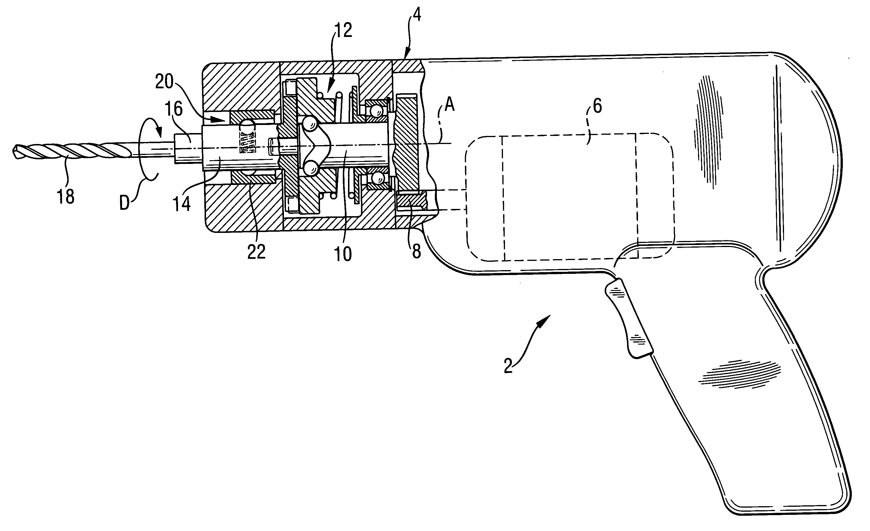
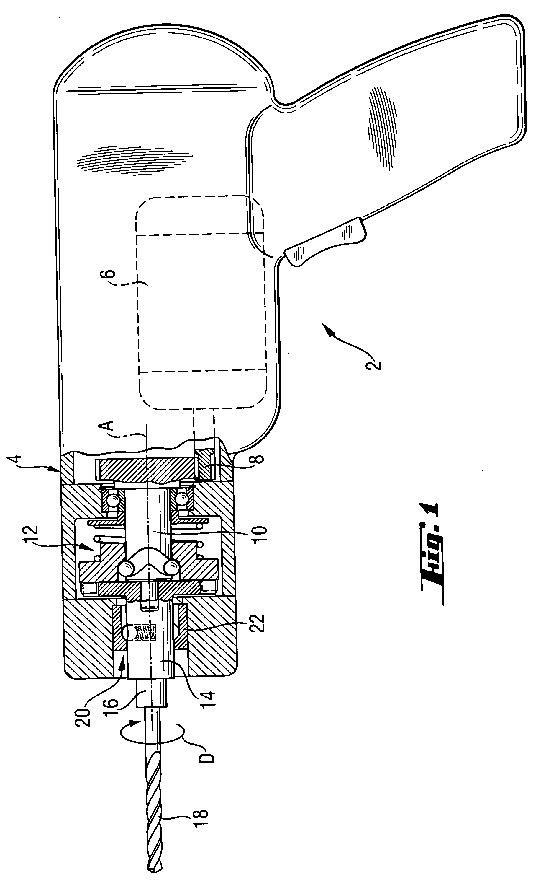
[0032] A hand-held power tool 2 according to the present invention, which is formed as a tangential percussion screwdriver and is shown in FIG. 1, has a housing 4 in which a universal motor 6 is located. The universal motor 6 drives, with its pinion 8, a drive spindle 10 in a rotational direction D about an axis A.

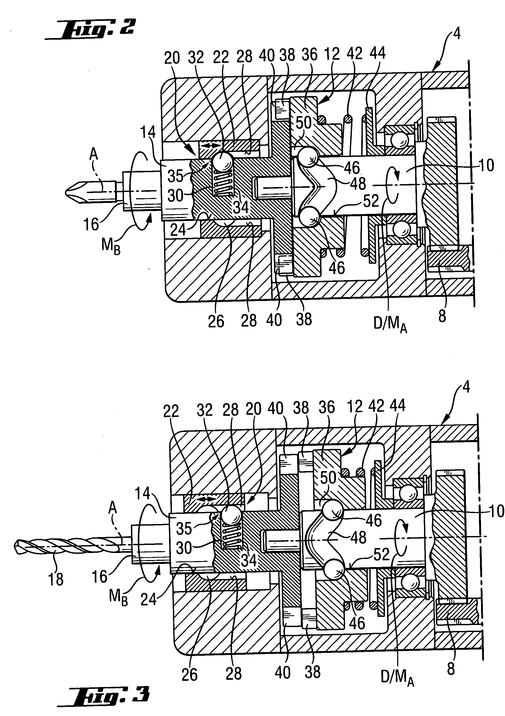
[0033] An angular torque generator, which is generally designated with a reference numeral 12, rotationally connects the drive spindle 10 with the drive spindle 14. A chuck 16, in which a working bit 18, e.g., formed as a screw bit or a drill bit, in particular, a twist drill bit can be received, is connected with the chuck 16 for joint rotation therewith.

[0034] A braking force generator, which is generally designated with a reference numeral 20, is provided on the working tool spindle 14. The braking force generator 20 applies to the working tool spindle 14 a braking force acting in a direction opposite the rotational direction D. The braking force generator 20 has a sl...


PUM

PropertyMeasurementUnit
Lengthaaaaaaaaaa
Forceaaaaaaaaaa
Torqueaaaaaaaaaa

Abstract

A hand-held power tool includes a motor (6) for applying a drive torque (MA) to the drive spindle (10) of the power tool, a working tool spindle (14) for driving a tool bit (18) in a rotational direction (D) and connectable with the drive spindle (10), an angular torque generator (12) for applying an angular torque pulse to the working tool spindle (14) when a resistance torque (MB) acting on the working tool spindle (10) reaches a predetermined threshold, and a braking force generator (20) arranged on the working tool spindle (14) for applying thereto a braking force in a direction opposite the rotational direction of the working tool spindle.

Description

BACKGROUND OF THE INVENTION [0001] 1. Field of the Invention [0002] The present invention relates to a hand-held power tool including a drive spindle, a motor for applying a drive torque to the drive spindle, a working tool spindle for driving a tool bit in a rotational direction and connectable with the drive spindle, a chuck for receiving the tool bit and connected with the working tool spindle for joint rotation therewith; an angular torque generator for applying an angular torque pulse to the working tool spindle when a resistance torque acting on the working tool spindle reaches a predetermined threshold. [0003] 2. Description of the Prior Art [0004] Hand-held power tools of the type described above permit switching, during an operation, from a continuous rotation to an intermittent rotation as soon as a resistance torque, which is generated by braking forces acting on the working tool spindle and the chuck, reaches a predetermined threshold. During the intermittent rotation, v...

Claims


Application Information

Patent Timeline
IPC IPC(8): B23B39/04
CPCB25B21/026B25D11/08Y10T408/16B25D2216/0023B25D2216/0038B25D16/00
Inventor SCHAD, HANSPETER
Owner HILTI AG
Why Eureka
Try Eureka