
Anode supported sofc with an electrode multifunctional layer

a fuel cell and multifunctional technology, applied in the direction of fuel cells, coatings, electrical devices, etc., can solve the problems of wasting resources, allowing electron transfer, cell deflecting or deformation,

Inactive Publication Date: 2006-02-02
VERSA POWER SYST
View PDF2 Cites 65 Cited by
  • Summary
  • Abstract
  • Description
  • Claims
  • Application Information

AI Technical Summary

Benefits of technology

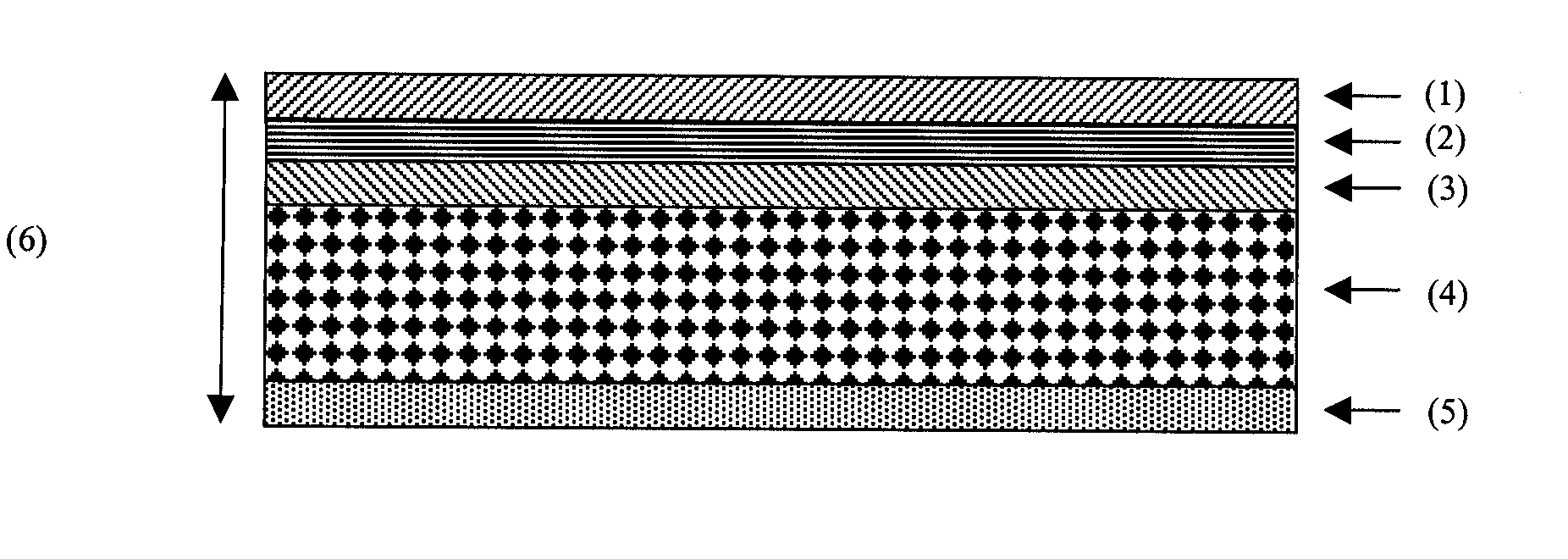
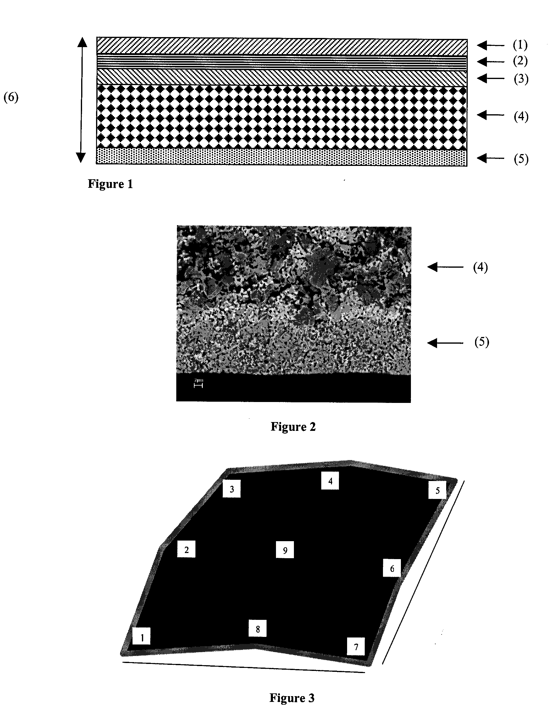
[0017] Preferably, the method further comprises the step of depositing an anode functional layer disposed between the anode substrate layer and the electrolyte. The multifunctional layer cermet prefer

Problems solved by technology

The membrane is coated with electrodes on both sides and permits transfer of ions of the oxidant, but does not permit transfer of electrons.
This differential shrinkage causes the cell to deflect or deform after cofiring.
However, ironing is a separate high temperature firing step that uses up resources and takes time.
As well each high temperature firing step coarsens the fuel cell microstructure slightly, which may degrade its performance.
If the fuel supply is cut off, such as may occur during emergency shutdown of an SOFC system, air can leak into the anode cavity, which causes rapid oxidation of the anode.
This is undesirable since there is a volume expansion when nickel oxidizes that can potentially damage the structure of the cell by causing layer delamination or electrolyte cracking.
If the electrolyte cracks, the fuel and oxidant gases will be able to mix directly, with potentially catastrophic results.
Because of the size of the openings, there may be difficulties with non-uniform gas distribution and anode contact.
As a result, this fuel cell is more complex than desired and requires many more steps to construct than is optimum.
As well, the small openings in the YSZ stress compensation layer may excessively limit the amount of fuel that can flow through this layer, which may cause mass transport losses to occur at higher current density of the operating conditions.

Method used


Image

  • Anode supported sofc with an electrode multifunctional layer
  • Anode supported sofc with an electrode multifunctional layer

Examples


example

[0037] This example discloses a method of making an anode-supported fuel cell with a multifunctional layer as described above and illustrates the ability of the multifunctional layer to enhance both cell flatness after cofiring and redox tolerance.

[0038] A SOFC as described above has been produced using tape casting and screen printing methods. The anode substrate is produced by a single layer tape cast of a 57 wt % NiO / 43 wt % YSZ slurry to produce green tape approximately 1 mm in thickness where NiO particles are several microns in size and the YSZ particles are less than 5 microns in size. The other fuel cell layers are deposited on this green (unfired) tape via screen printing. The anode functional layer, electrolyte and cathode functional layers are deposited sequentially on one side of the anode substrate while the electrode multifunctional layer is deposited on the other side of the anode substrate. The anode functional layer is a fine structured 57 wt % NiO / 43 wt % YSZ mixt...


PUM


Abstract

The invention is directed to a fuel cell which is configured to avoid deformation caused by differential shrinking, and which mitigates the damage caused by the introduction of an oxidizing environment in the anode cavity during the operation of the fuel cell. The fuel cell has a cathode, an electrolyte, an anode and a porous multifunctional layer disposed on the anode opposite to the electrolyte. The porous multifunctional layer comprises a cermet which has thermal expansion and shrinkage behaviour substantially similar to the other fuel cell layers.

Description

CROSS REFERENCE TO RELATED APPLICATIONS [0001] This application claims the priority benefit of U.S. Provisional Application No. 60 / 521,961 filed on Jul. 27, 2004 entitled “Anode Supported SOFC With An Electrode Multifunctional Layer”, the contents of which are incorporated herein by reference.FIELD OF THE INVENTION [0002] The present invention relates to an anode-supported solid oxide fuel cell having an electrode multifunctional layer. BACKGROUND OF THE INVENTION [0003] Solid oxide fuel cells (SOFCs) are an energy generation technology that produces electricity quietly, cleanly and efficiently through the direct electrochemical combination of a fuel with an oxidant. This direct production of electricity effectively bypasses the conversion of the fuel's chemical energy into thermal and mechanical energy and thus allows higher theoretical efficiencies to be achieved. The reactants (fuel and oxidant) are supplied to the cell through manifolds and flow fields that direct the reactants ...

Claims


Application Information

Patent Timeline
IPC IPC(8): H01M8/10B05D5/12H01M4/86
CPCH01M4/8621H01M4/8885H01M4/9066Y02E60/525H01M8/1213H01M8/1226Y02E60/521H01M8/0297Y02E60/50
Inventor WALDBILLIG, DAVIDWOOD, ANTHONYJOIA, TAHIRTANG, ERIC
Owner VERSA POWER SYST
Learn More