The quick distribution of modern transmission technologies that are, for example, used in a
mobile radio transmission, present a great challenge for the design of high-frequency receivers (RF receivers).
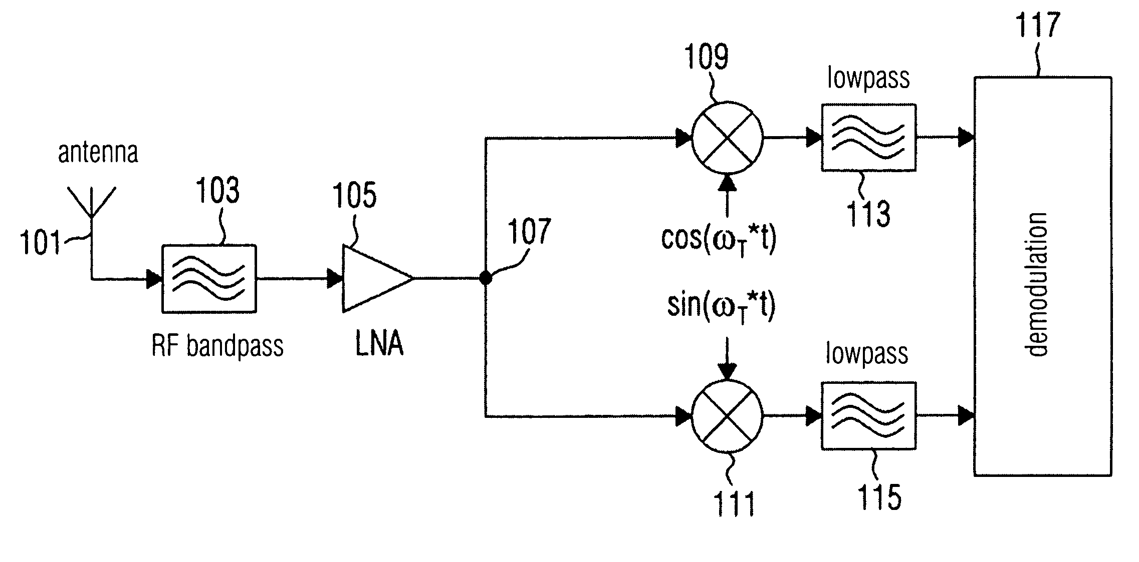
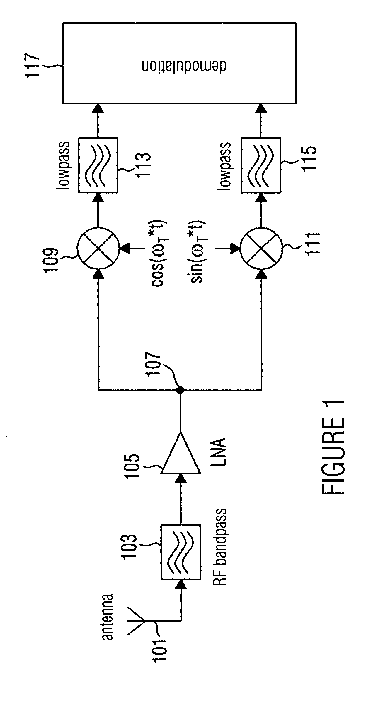
The
disadvantage about the homodyne
receiver illustrated in FIG. 1 is that the two control signals that are required for the mixers 109 and 111 have to be generated by a
local oscillator, wherein the
local oscillator comprises an oscillation frequency which is equal to the carrier frequency.
It turns out to be difficult to generate a high-frequency tunable oscillator frequency.
This leads to an increased bit error probability (BER).
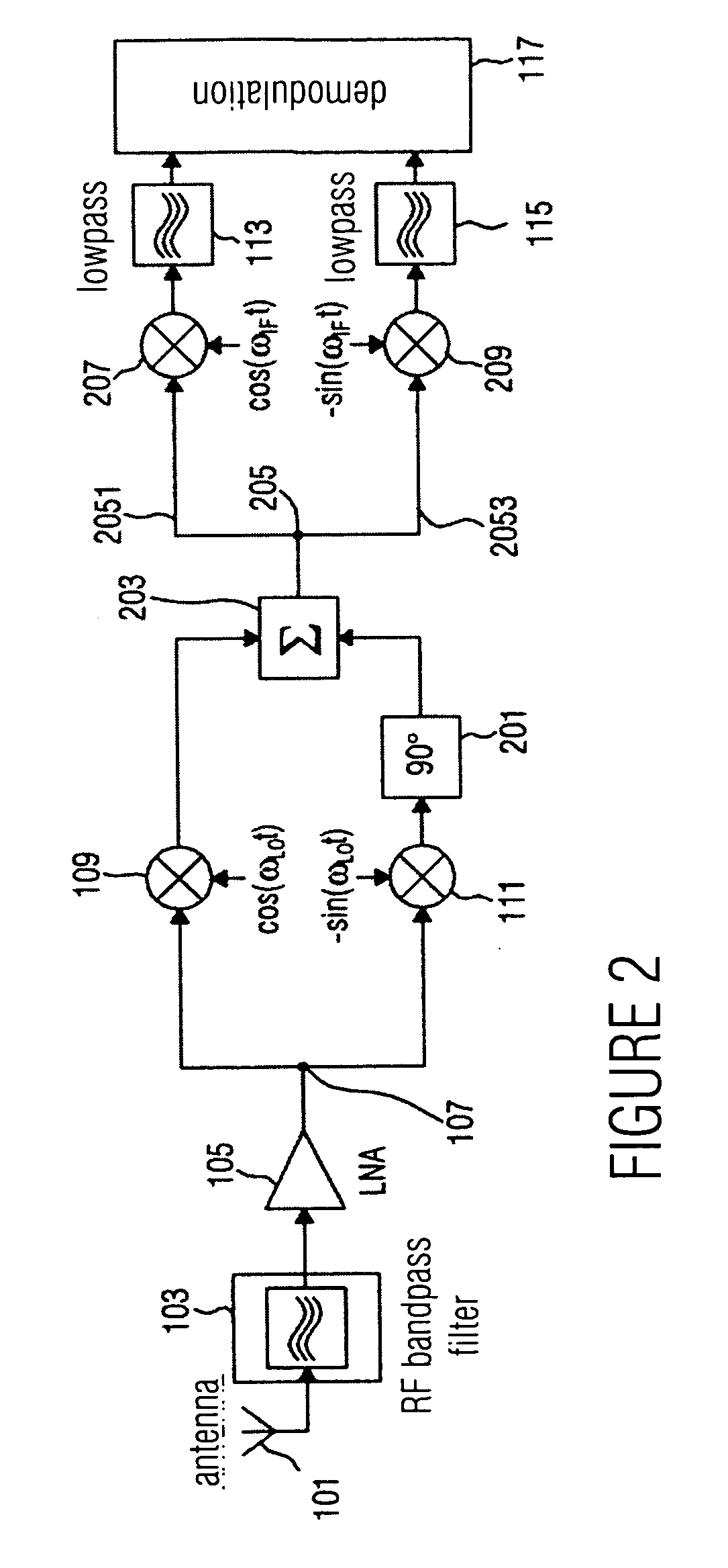
A further
disadvantage of the homodyne
receiver illustrated in FIG. 2 is that after the
baseband mixing
DC voltage proportions result that occur as interference signals in the base band and interfere with the desired signals.
These
DC voltage proportions may, however, be eliminated with the help of a
capacitor (AC
coupling), but here a narrow-band filtering is required, requiring a long
settling time, which may, for example, with a TDD signal (TDD=
time domain duplex) lead to the fact that the signal may not be received in time.
A further
disadvantage of the homodyne
receiver illustrated in FIG. 1 is a
noise which is in particular multistage-amplified at a respective output of the respective mixer 109, 111.
If, for example, a
phase difference between the two control signals that are used for a multiplication with the respective partial receive signal in the respective mixer 109 and 111 is present, then the quadrature components applied to the inputs of the demodulator 117 are not exactly phase-shifted to each other by 90 degrees, which leads to an increase of the bit error probability.
With a deviation of the oscillator frequency from the frequency of the carrier, the signal is further not exactly shifted into the base band, so that a subsequent
demodulation is complicated, which leads to an increase of the bit error probability.
In addition to this, the use of a homodyne receiver, as it is illustrated in FIG. 1, is problematic if receive signals have to be downward-mixed, who respectively have a different associated carrier frequency, as it is for example the case in a
GSM or also a UMTS receive signal, as the
local oscillator would respectively have to be tunable in a wide frequency range which is difficult to realize in practice at low cost, however.
In order to select a channel it is necessary, however, to select only one signal proportion, which is not possible, however, by a mere filtering of the IF signals.
A disadvantage of this approach is, however, that such filters are difficult to manufacture in MOS technology, as a manufacturing of coils with a sufficient quality is difficult.
One disadvantage of the
heterodyne receiver illustrated in FIG. 2 or in FIG. 3 is, that with a mismatching between the I component at the output of the mixer 301 and the Q component at the output of the mixer 303 a low
image signal attenuation is achieved.
A further disadvantage of the
heterodyne receiver illustrated in FIG. 2 or in FIG. 3 is that they are not flexible enough in order to, for example, convert high-frequency input signals to the first intermediate frequency when different carrier frequencies are associated with the input signals, as it is for example the case with a multi-standard reception.
It is a further disadvantage of the
heterodyne receivers according to the prior art illustrated in FIG. 2 and in FIG. 3, that they are expensive and difficult to be integrated due to the employed analog components.
In addition to this, with the employed analog mixers 109, 111, 301, 303, 207 and 209 no exact multiplication is possible, so that an exact intermediate
frequency conversion of the respective signals may not be achieved, which leads to an increase of the bit error probability.
In addition to this, at the non-linearities of the analog components further inter-modulation frequencies are generated which interfere and lead to a further increase of the bit error probability.
In addition to this, a slight deviation of the partial receive signals applied to the inputs of the summator 203 with regard to the phase or the amplitude, have a substantial effect on the image frequency rejection, which leads to a further increase of the bit error probability.
For this reason it is compulsory to implement the paths via which the two partial receive signals are transmitted as symmetric as possible with regard to an attenuation and to use oscillators that are as stable as possible for generating the respective control signals for the mixers, which leads to a significant cost increase of such heterodyne structures.
This is very expensive, however, as the demands on the mixer are increased due to a broad-band operation range, if the receive structures are used for downward mixing receive signals respectively comprising different carrier frequencies.

