

Optical measuring device for substances in vivo
- Summary
- Abstract
- Description
- Claims
- Application Information
AI Technical Summary
Benefits of technology
Problems solved by technology
Method used
Image

Examples
embodiment 1
(Embodiment 1)
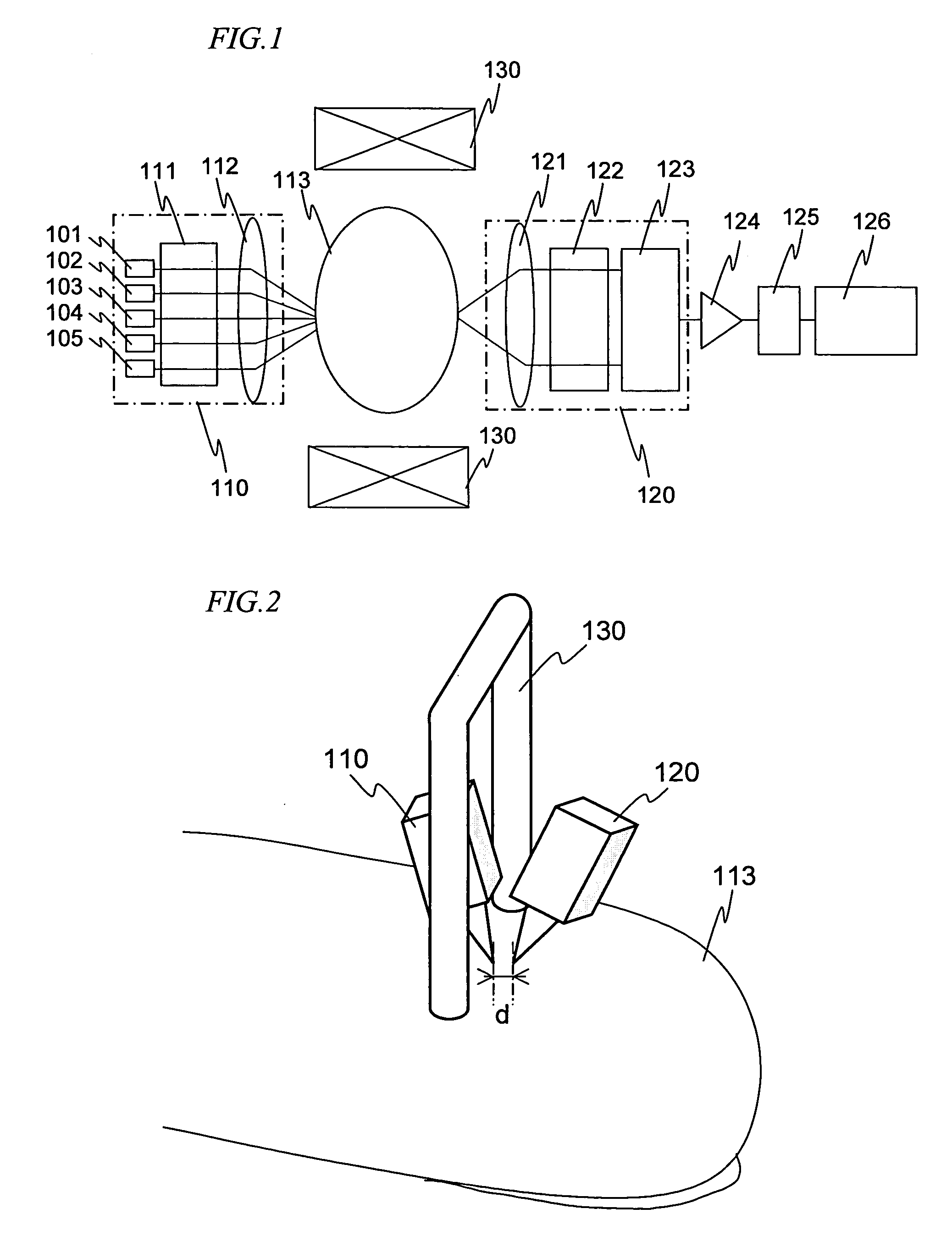
[0029] A first preferred embodiment of the present invention will be described with reference to FIG. 1. FIG. 1 is a block diagram illustrating the principle of a transmission type concentration measuring device for substances in vivo using Faraday effect. Reference numerals 101 through 105 denote laser diodes of 780 nm, 830 nm, 870 nm, 1300 nm and 1500 nm, respectively, in wavelength.
[0030] The laser diodes are amplitude-modulated with different frequencies fi, respectively 10 kHz, 12 kHz, 14 kHz, 16 kHz and 18 kHz, for example. Reference numeral 111 denotes a lens and 112, a polarizer. The laser diodes 101 through 105, the lens 111 and the polarizer 112 constitute a light source system 110.
[0031] The output lights of the laser diodes 101 through 105 are collimated by using the lens 111 and, after passing the polarizer 112, irradiate an object region (e.g. a finger) 113. The lights having passed the object region 113, after being collimated by a lens 121, are guided...
embodiment 2
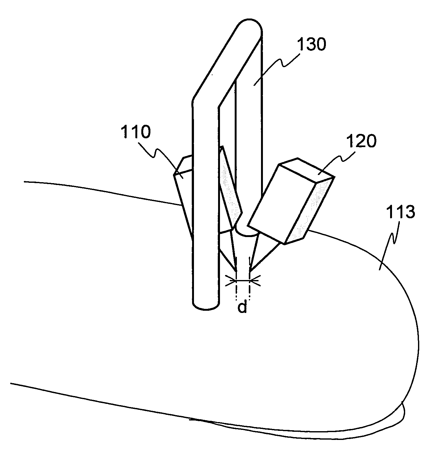
(Embodiment 2)
[0035] A second preferred embodiment of the invention will now be described with reference to FIG. 2. FIG. 2 is a block diagram illustrating the principle of a reflection type concentration measuring device for substances in vivo using Faraday effect. While the arrangement of Embodiment 1 is to let lights pass the object region, this second embodiment uses a reflection type arrangement. The hardware configuration is almost the same as that of Embodiment 1. The light source system 110 and the detector system 120 are arranged on the same side with respect to the object region 113. Incidentally, the light source system 110 and the detector system 120 are the same as their respective counterparts in FIG. 1. The focal position of the lens 111 and that of the lens 121 may be the same, but deviating one from the other would increase the contribution of blood vessels within the epidermis to signals. For this reason, the distance between the focal positions of the two lenses he...
embodiment 3
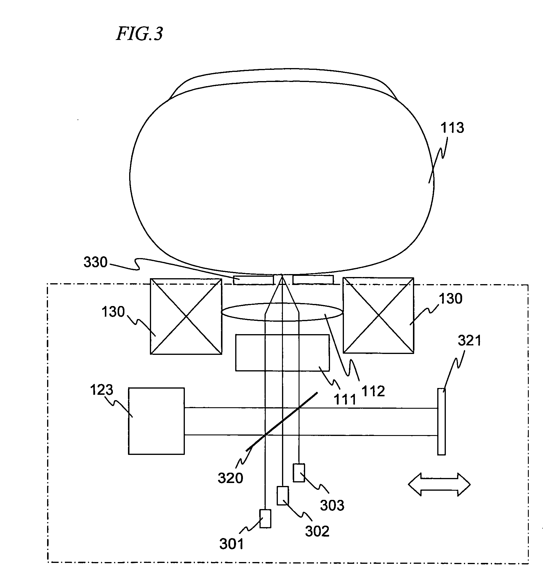
(Embodiment 3)
[0039] A third preferred embodiment of the invention will be described with reference to FIG. 3. FIG. 3 is a block diagram illustrating the interfering effect of low-coherence light sources and the principle of a concentration measuring device for substances in vivo using the effect of interference by low-coherence light sources and Faraday effect. The output lights of super-luminescent diodes 301, 302 and 303 of 840 nm, 1310 nm and 1550 nm in wavelength, after being let pass a half mirror 320 and a polarizer 111, are focuses on the surface of the object, for instance the surface of a finger 113, by using a lens 112. The reflected lights from the surface of the finger 113 are again collimated by the lens 112 and, after passing the polarizer 111, are reflected by the half mirror 320 to come into incidence on the photodiode 123. On the other hand, part of the lights emitted from the super-luminescent diodes 301 through 303 is separated by the half mirror 320, reflected b...
PUM
 Abstract
Description
Claims
Application Information