Variable attenuation circuit having large attenuation amount with small circuit size

Inactive Publication Date: 2006-02-09
ALPS ALPINE CO LTD
View PDF1 Cites 3 Cited by
  • Summary
  • Abstract
  • Description
  • Claims
  • Application Information

AI Technical Summary

Benefits of technology

[0017] According to the fourth aspect of the invention, the amplifying circuit is interposed between the attenuation circuit and the

Problems solved by technology

Accordingly, the circuit size becomes large and th

Method used


Image

  • Variable attenuation circuit having large attenuation amount with small circuit size
  • Variable attenuation circuit having large attenuation amount with small circuit size

Examples


Embodiment Construction

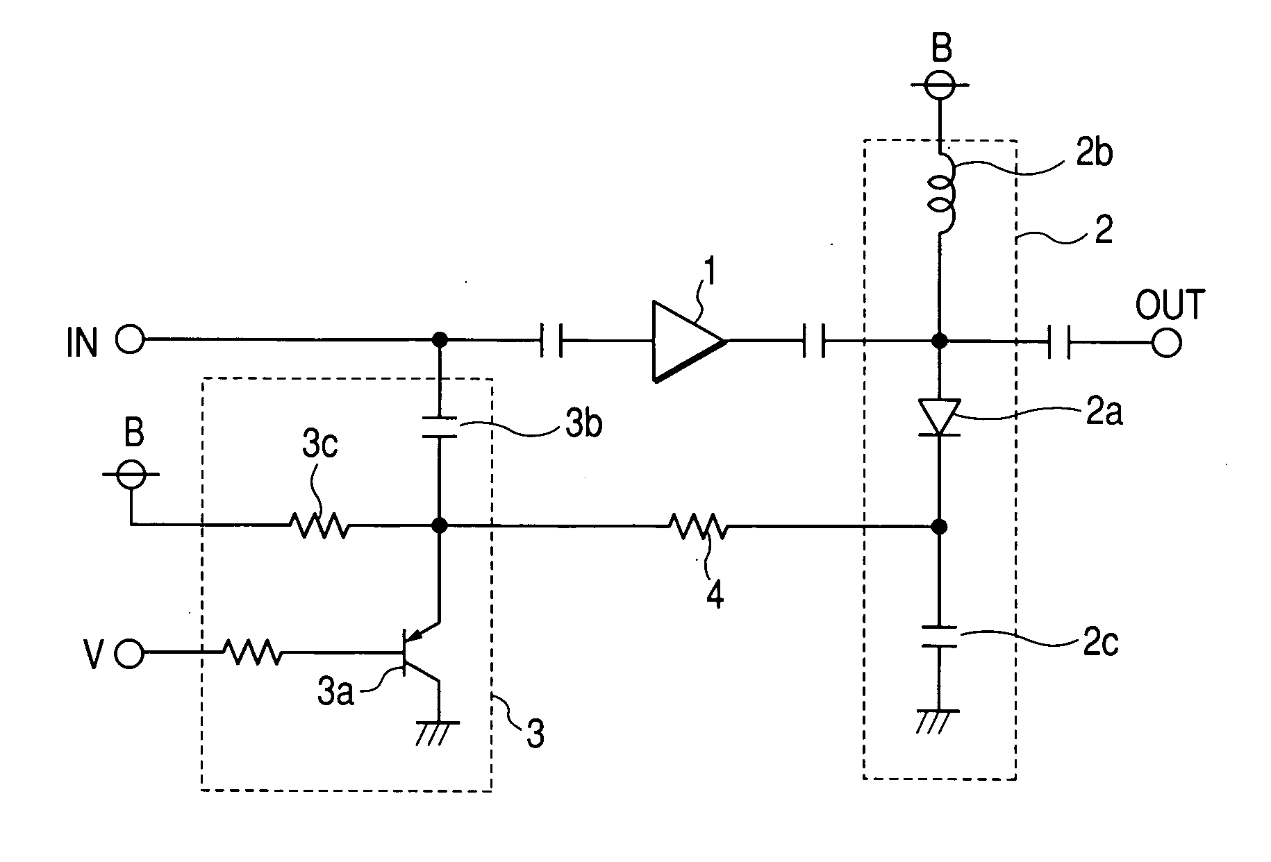
[0020] A variable attenuation circuit of the present invention will now be described with reference to FIG. 1. An attenuation circuit 2 is connected to the post-stage of an amplifying circuit 1 and an attenuation control circuit 3 is connected to the pre-stage of the amplifying circuit 1. A PIN diode 2a is used for the attenuation circuit 2 as a first semiconductor variable impedance element, and an anode of the PIN diode 2a is coupled to a signal line on the output side of the amplifying circuit 1. Further, the anode of the PIN diode 2a is pulled up to a power supply B via a choke inductor 2b and a cathode thereof is grounded by a direct current (DC) blocking capacitor 2c in radio-frequency wise.

[0021] A PNP transistor 3a is used for the attenuation control circuit 3 as a second semiconductor variable impedance element. A collector of the PNP transistor 3a is grounded. Further, an emitter of the PNP transistor 3a is coupled to the signal line on the input side of the amplifying ci...


PUM


Abstract

A variable attenuation circuit includes an attenuation circuit which has a first semiconductor variable impedance element, and an attenuation control circuit of which the impedance is changed by a control voltage to be applied from the outside and which has a second semiconductor variable impedance element for controlling the impedance of the first semiconductor variable impedance element. The attenuation circuit and the attenuation control circuit are connected in cascade. Therefore, signals can be attenuated by the attenuation control circuit, in addition to the attenuation circuit.

Description

BACKGROUND OF THE INVENTION [0001] 1. Field of the Invention [0002] The present invention relates to a variable attenuation circuit that is used for a television tuner or the like. [0003] 2. Description of the Related Art [0004] A variable attenuation circuit according to the related art has a configuration in which a first attenuator unit 41a, an RF amplifying circuit 42, and a second attenuator unit 41b are connected in cascade, as shown in FIG. 2. Both attenuator units 41a and 41b have the same circuit configuration and thus only the first attenuator unit 41a will be described. A PIN diode Dla is provided between an input terminal INa and an output terminal OUTa of the first attenuator unit 41a. An anode of the PIN diode Dla is connected to the input terminal INa via a connection capacitor C1a and a cathode of the PIN diode D1a is connected to the output terminal OUTa via a capacitor C2a. [0005] The anode of the PIN diode Dla is applied with a control voltage v2 via a driving res...

Claims


Application Information

Patent Timeline
IPC IPC(8): H01P1/22
CPCH03H7/255
Inventor ENDO, MASAAKIYAMAMOTO, MASAKI
Owner ALPS ALPINE CO LTD
Why Eureka
Try Eureka