
Support device for chromophore elements

a technology of support device and chromophore, which is applied in the direction of fluorescence/phosphorescence, instruments, material analysis, etc., can solve the problems of likewise troublesome separation and difficult separation, and achieve the effect of simple, effective and inexpensiv

Inactive Publication Date: 2006-02-09
GENEWAVE SAS
View PDF4 Cites 8 Cited by
  • Summary
  • Abstract
  • Description
  • Claims
  • Application Information

AI Technical Summary

Benefits of technology

[0009] A particular object of the invention is to provide a solution to this problem which is simple, effective, and inexpensive, enabling the reflection of excitation light by the support to be cancelled or at least reduced, while conserving the advantage that results from reflecting the emitted fluorescence.
[0014] In the support of the invention, reflection of the excitation light towards the means for collecting the fluorescence from the chromophore elements is greatly decreased or even cancelled, and the intensity of the fluorescence is increased, thus making it much easier to detect and measure said fluorescence.
[0016] When the support is transparent at the excitation wavelength, this makes it possible to cancel reflection at said wavelength at the face of the support opposite from the face carrying the chromophore elements.
[0020] This very simple embodiment benefits from the advantages that result from reflecting the emitted fluorescence (doubling the intensity that can be picked up), while avoiding the drawbacks of the excitation light being reflected by the reflective layer integrated in the support.
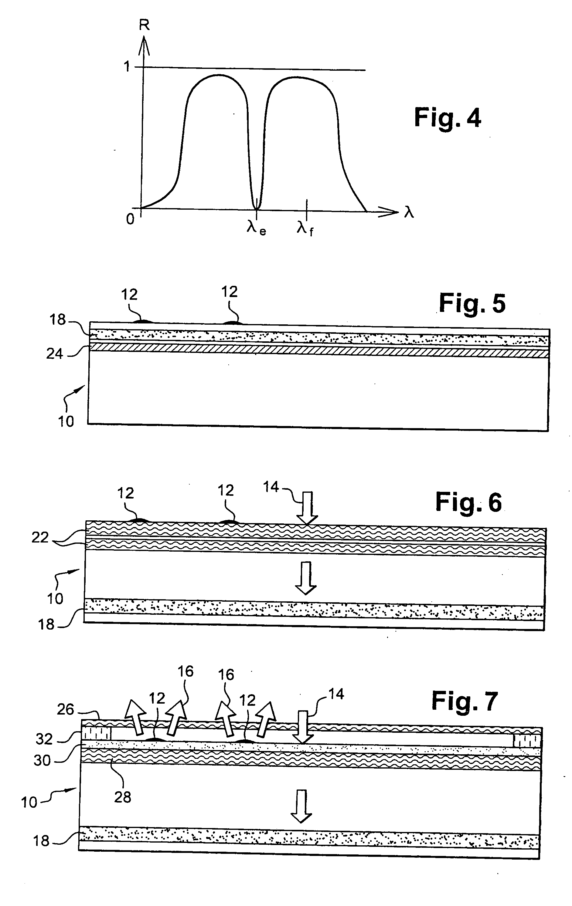
[0033] The above-specified absorbent layer then has different absorption bands corresponding to the excitation wavelengths and may be formed for this purpose either out of a single suitable ingredient, or else out of a mixture of ingredients having different absorption bands. Similarly, the above-specified antireflection layer may be formed by a stack of layers presenting low reflection for the various excitation wavelengths. It is also possible to use a single antireflection layer having a refractive index close to the square root of the index of the material of the support, and thickness determined so as to minimize reflection at a wavelength lying between two excitation wavelengths that are relatively close to each other, the spectrum width of the reflection minimum typically being more than 100 nanometers (nm) in the visible spectrum, thus making it possible, for example, to determine a thickness for the layer corresponding to a reflection minimum centered on 580 nm when using excitation wavelengths of 532 nm and 633 nm.
[0034] In general, the invention makes it possible significantly to increase the signal-to-noise ratio and to minimize the background signal in light sensors for detecting and measuring the fluorescence emitted by chromophore elements in a biochip type device.

Problems solved by technology

Nevertheless, in the light that is picked up by the collector and measurement means, it remains necessary to separate any excitation light reflected by the support from the emitted fluorescence, and for this purpose dichroic or absorbent filters are used, but such separation is difficult and the excitation light is not totally rejected.
When the support is a transparent thin plate with parallel faces, the reflection of excitation light by the face of the plate opposite from the face carrying the chromophore elements is of comparable intensity (4% of 96%, i.e. 3.84%), and is likewise troublesome.

Method used


Image

  • Support device for chromophore elements
  • Support device for chromophore elements
  • Support device for chromophore elements

Examples


Embodiment Construction

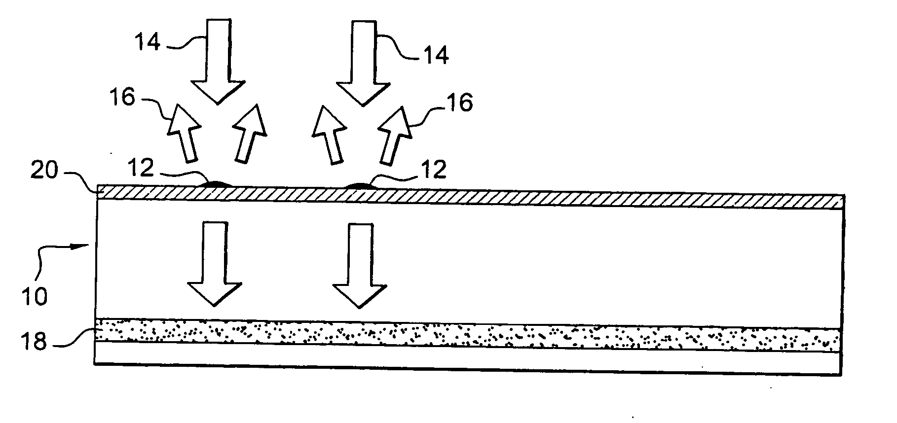
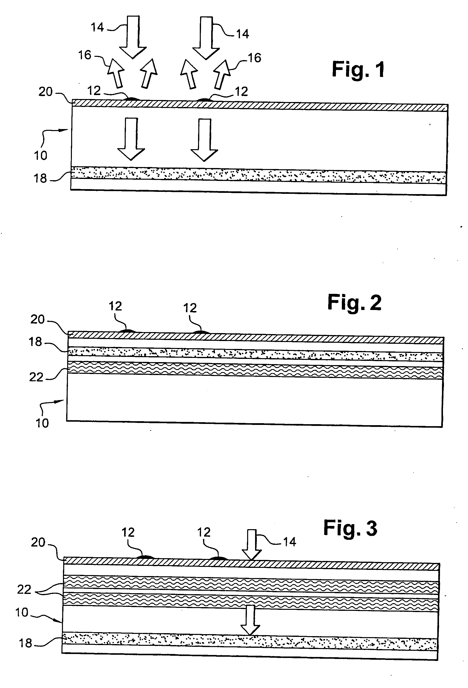
[0039] In FIG. 1, reference 10 is an overall reference for a support of the invention, which in this embodiment is constituted essentially by a plate of material having a refractive index n, with a top face for carrying chromophore elements 12, e.g. chemical or biological molecules as mentioned above, and which are secured in an array on the top face of the support 10.

[0040] These chromophore elements 12 are illuminated by excitation light 14, generally monochromatic light or narrow spectrum light, possibly polarized (laser light), and at an angle of incidence that is accurately defined and that is often substantially perpendicular to the surface of the support 10, and in response, these chromophore elements 12 emit fluorescence 16 at a wavelength that depends on the nature of the chromophore elements 12, and that is longer than the wavelength of the excitation light 14.

[0041] The intensity of the fluorescence emitted by the chromophore elements 12 is very weak compared with that ...


PUM


Abstract

A support for chromophore elements, which elements are for being illuminated by excitation light to emit fluorescence at a wavelength different from that of the excitation light, the support including an internal reflective layer reflecting the light emitted by the chromophore elements, a layer of absorbent material absorbing the excitation wavelength, and a layer of material constituting an antireflection layer at said wavelength in order to avoid excitation light being reflected by the support and being added to the fluorescence emitted by the chromophore elements.

Description

[0001] The invention relates to a support device for chromophore elements, the device being of the type commonly referred to as a “biochip”. BACKGROUND OF THE INVENTION [0002] Such devices comprise a support constituted by a generally multilayer substrate having one face carrying chromophore elements which are chemical or biological molecules or dyes added or grafted to chemical or biological molecules, or semiconductor nanostructures such as quantum boxes or wires secured to such molecules, such chromophore elements emitting fluorescence at a wavelength that depends on their nature when they are excited by suitable light, with detection of such fluorescence making it possible, on the support, to identify and locate molecules that have reacted to given treatments. [0003] Means have already been proposed, in particular in applications WO-A-02 / 516912, FR 01 / 15140, and FR 02 / 10285 in the name of the same inventors, for increasing the efficiencies of light excitation and emission of flu...

Claims


Application Information

Patent Timeline
IPC IPC(8): G01N21/01G01N21/64G01N21/77
CPCG01N21/7703G01N21/645
Inventor WEISBUCH, CLAUDE
Owner GENEWAVE SAS
Learn More