
Two-dimensional image projection system

a projection system and image technology, applied in the field of image projection system, can solve the problems of limited light direction, high power consumption, limited light efficiency, etc., and achieve the effect of easy control of the light intensity of the displayed imag

Active Publication Date: 2006-02-09
STEREO DISPLAY
View PDF2 Cites 61 Cited by
  • Summary
  • Abstract
  • Description
  • Claims
  • Application Information

AI Technical Summary

Benefits of technology

[0007] When the array of micromirror array lenses is applied to the conventional two-dimensional display devices, such as projector and / or projection television, the brightness of the projected image and power consumption of the display device are greatly improved by increasing light efficiency over prior art DMD array devices. The array of micromirror array lenses can use most incident light by adopting an optimized Random Scanning Technique. In accordance with this technique, a random scanning processor analyses brightness of each frame, and optimizes the focusing position and scanning speed of each micromirror array lens. For the purposes of the present invention, “random” means scanning is not sequential. Accordingly, in order to optimize the set of micromirror array lens combinations which can minimize the movement, minimize construction and destruction of the micromirror array lens, and the minimize scanning length for a frame rate, each micromirror array lens: (a) has an arbitrary number of micromirors; (b) scans a plane with different speed; and (b) focus light at random positions in the plane.
[0008] The random scanning technique also enables the number of micromirrors to be less than the number of image pixels without deterioration of the resolution of projected images. The gray scale of each pixel is easily achievable by controlling scanning speed and / or by controlling the number of micromirrors of each micromirror array lens.
[0012] (1) It improves brightness and power consumption of a two-dimensional image projection systems;
[0016] (5) A group of micromirror array lenses of the lens array can be controlled to scan the same point simultaneously to easily control the light intensity of the displayed image.

Problems solved by technology

Since the DMD array is merely an array of optical switches, the direction of light is limited.
When the DMD array is applied to a two-dimensional image projection device, such as projectors and projection televisions, simple “on-off” behavior limits its light efficiency and becomes the main reason for its high power consumption.
Although micromirror array lens is capable of changing its focal length in a very sort amount of time, the micromirror array lens is not capable of being used in two-dimensional display devices because its optical axis is fixed.
The additional optical components deteriorate the light efficiency, and increase complexity and cost of the optical system.

Method used


Image

  • Two-dimensional image projection system
  • Two-dimensional image projection system
  • Two-dimensional image projection system

Examples


Embodiment Construction

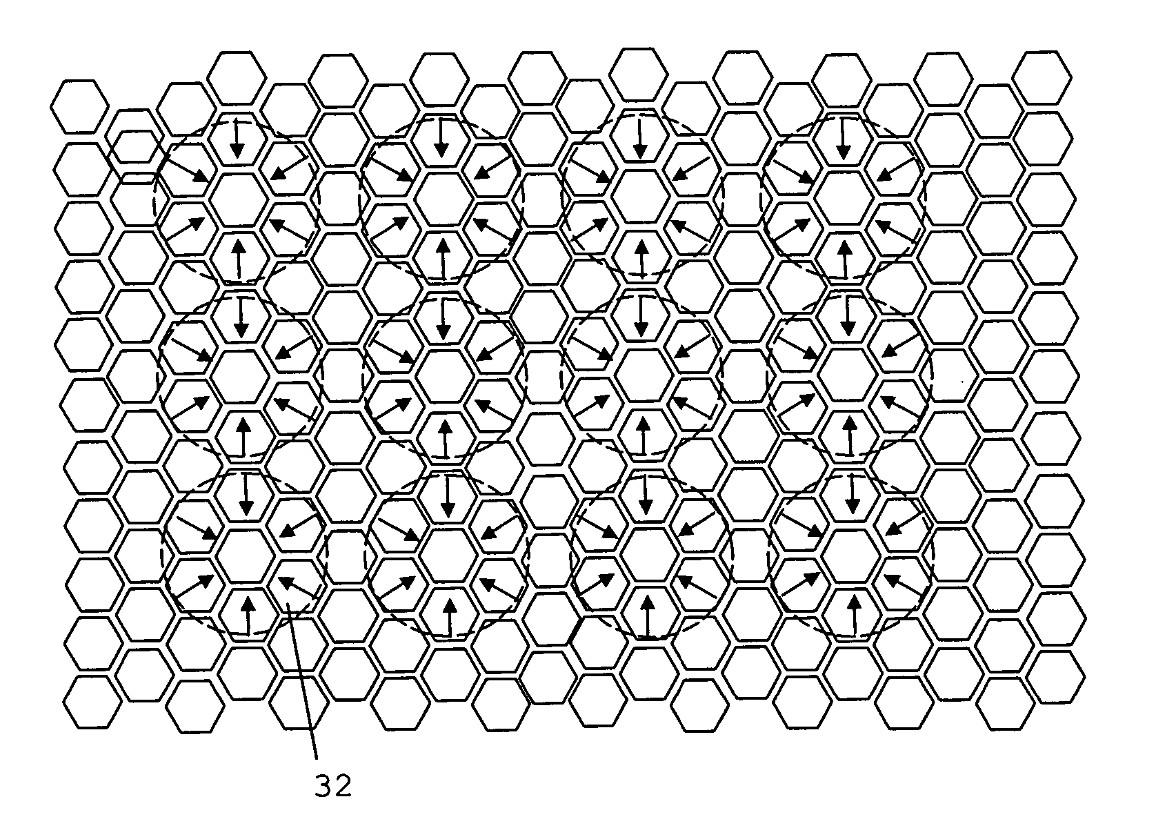
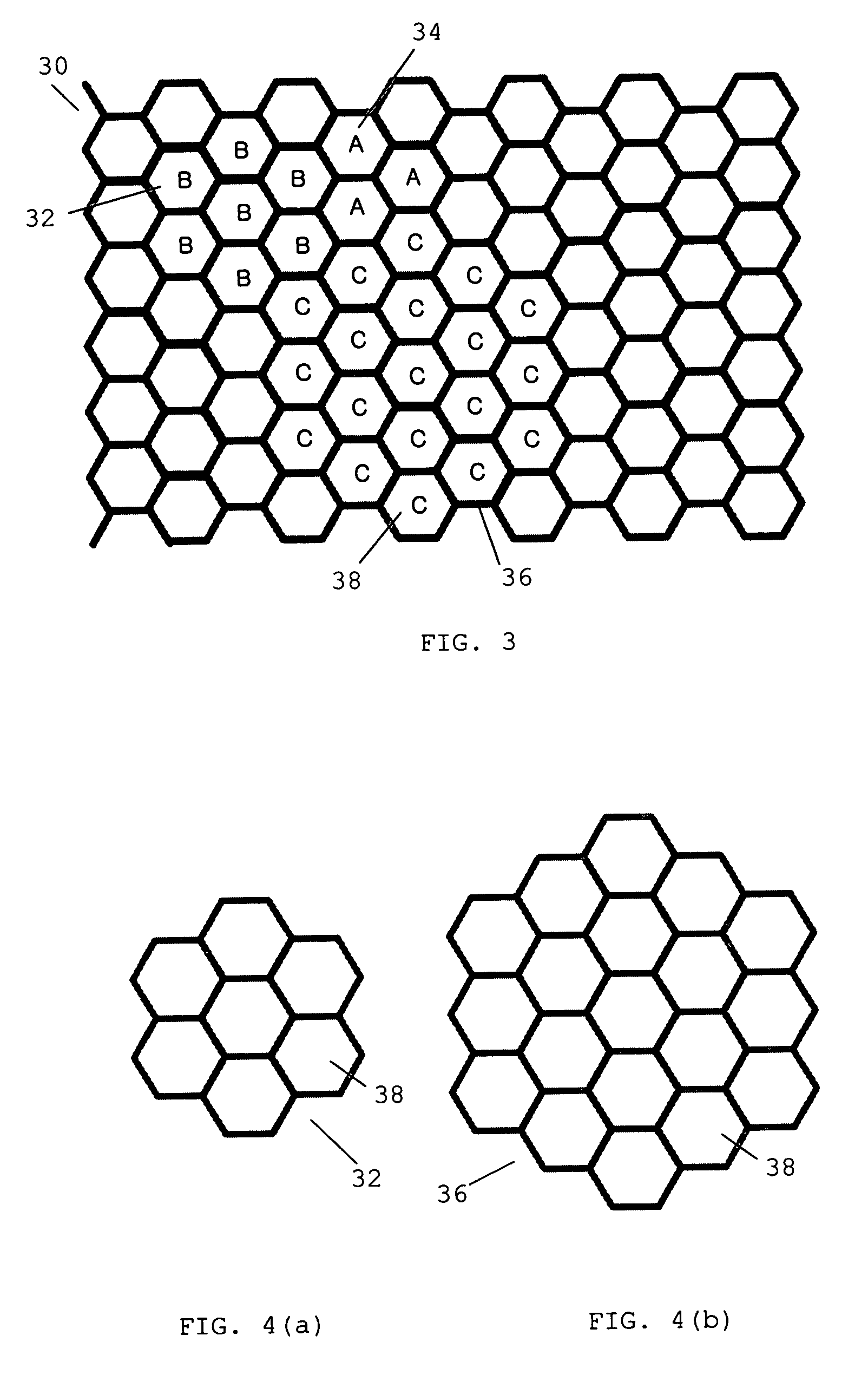
[0030] In a particularly preferred embodiment of the invention there is provided a two-dimensional image projection device comprising an array of micromirror array lenses. Each micromirror array lens comprises a plurality of micromirrors, whose configurations may be adjusted to change the focal length, optical axis, lens size, the number of lenses, shape of lens, and others of the micromirror array lens. When applied to conventional two-dimensional display devices, the array of micromirror array lenses greatly improve the brightness of the projected image and the power consumption of the display device by increasing light efficiency.

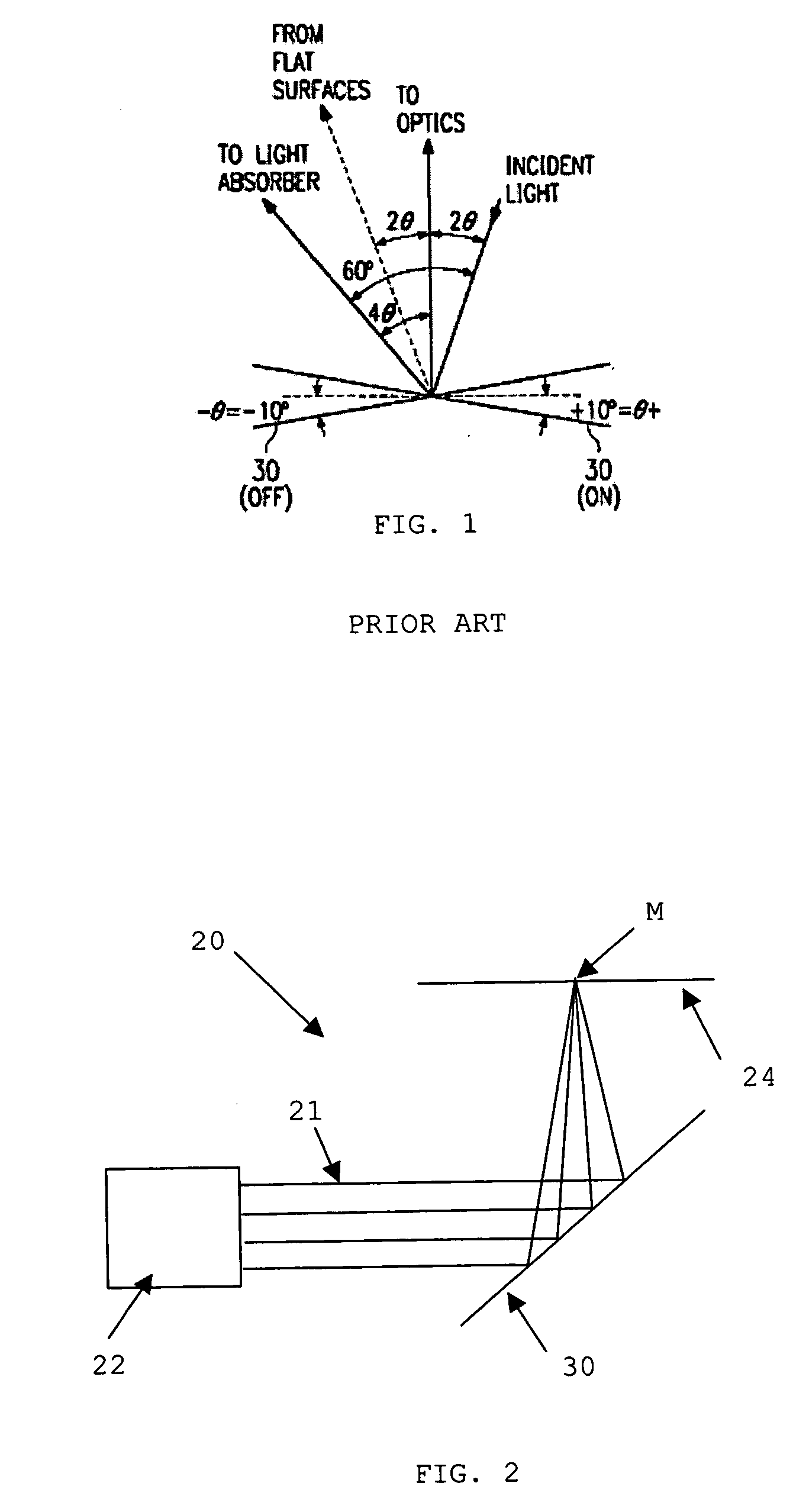
[0031]FIG. 2 a two-dimensional image projection device 20 comprising a light source 22, a lens array 30, and a projection plane 24. The light source 22 may be any conventional light source, such as a metal halide with a color wheel, a light emitted diode, a three (Red, Green, Blue) laser diode, or any other suitable light source. The light source genera...


PUM


Abstract

A two-dimensional image projection device using array of micromirror array lenses and a random scanning technique is invented. Using the random scanning technique, the light efficiency is nearly doubled than that of the prior art. The invention makes a brighter and less power consuming display device possible. Because each micromirror array lens of array of micromirror array lenses can scan whole image plane, a fast self diagnosis and correction technique can be introduced in displaying device. The Self diagnosis and correction technique makes display device to maintain image quality even a few tens percent of micromirrors do not work properly. Owing to the scanning characteristics of micromirror array lens, the image projection device can express the same number of pixels image with less number of micromirrors than the prior art. This also enables small sized two-dimensional image projector, which can be incorporated in portable electronic equipments.

Description

FIELD OF THE INVENTION [0001] The present invention relates generally to an image projection system, and more specifically, to a two-dimensional image projection system comprising an array of micromirror array lenses. BACKGROUND [0002] Spatial light modulators (SLM) have been used in projection display systems to increase image resolution and display brightness. For example, a Digital Micromirror Device (DMD) array, as described in U.S. Pat. Nos. 5,535,047 and 6,232,936, was used for two-dimensional image projection devices. According to this teaching, each micromirror of the DMD array has single-degree-of-freedom, rotation about an axis, and works as a simple optical switch. Since the DMD array is merely an array of optical switches, the direction of light is limited. As shown in FIG. 1, the DMD array has only two positions; one is the “on” position and the other is the “off” position. When the DMD array is applied to a two-dimensional image projection device, such as projectors an...

Claims


Application Information

Patent Timeline
IPC IPC(8): G02B26/00
CPCG09G3/346G09G2330/08H04N9/3194H04N9/3173H04N9/3161G02B26/0841
Inventor CHO, GYOUNG ILKIM, TAE HYEONSEO, CHEONG SOO
Owner STEREO DISPLAY
Learn More