
Magnetic memory using single domain switching by direct current

a single-domain switching and magnetic memory technology, applied in the direction of magnetic field-controlled resistors, digital storage, instruments, etc., can solve the problems of high external current, difficult to overcome significant obstacles, and difficult to achieve fabrication requirements, so as to achieve a stable head-to-head magnetization configuration, reduce the effect of magnetostatic interaction and eliminate cross-talk

Inactive Publication Date: 2006-02-09
UCHICAGO ARGONNE LLC
View PDF1 Cites 20 Cited by
  • Summary
  • Abstract
  • Description
  • Claims
  • Application Information

AI Technical Summary

Benefits of technology

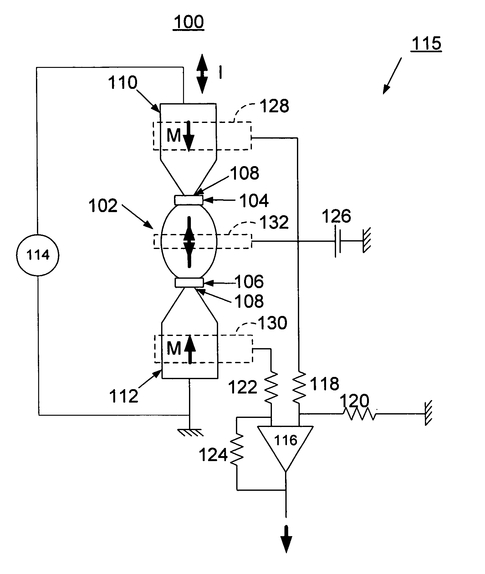
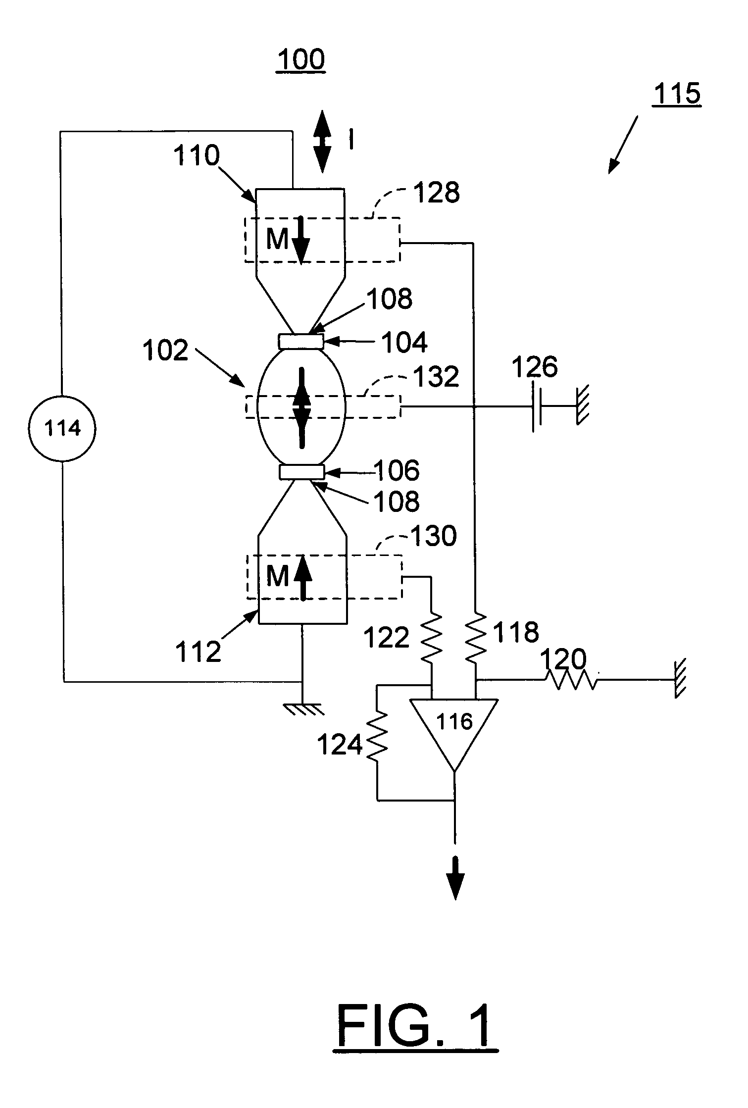
[0011] In accordance with features of the invention, a magnetic memory is provided that substantially eliminates cross-talk by switching a single domain island through current induced domain wall motion for writing information with current polarity. This is achieved with a current source and current leads with well-defined magnetization, which generate a well-defined spin polarized current at the location of the single domain island.
[0012] The magnetic memory of the invention uses a half-circle or U-shaped architecture with an exchange biasing pad, incorporating any suitable antiferromagnetic material such as a FeMn exchange biasing pad, that effectively generates a stable head-to-head magnetization configuration. The magnetic memory also includes nanometer scale notches in order to minimize magnetostatic interaction between a single domain memory element and the spin current sources and to effectively trap the magnetic domain wall. Reading the bit can be carried out by anisotropic magnetoresistance, or by other means of determining the magnetization orientation through resistance measurements, such as a spin valve or a magnetic tunneling junction.

Problems solved by technology

However, a potential drawback for this technique is the need for a high external current to induce magnetization reversal.
There are significant hurdles to be overcome, such as the reduction of cross-talk between the magnetic memory elements during the write cycle due to the high density packing.
One recently proposed voltage controlled rotation (VCR) is very appealing, but the fabrication requirements appear to be quite stringent.

Method used


Image

  • Magnetic memory using single domain switching by direct current
  • Magnetic memory using single domain switching by direct current
  • Magnetic memory using single domain switching by direct current

Examples


Embodiment Construction

[0017] In accordance with features of the invention, a magnetic memory device is provided that substantially eliminates cross-talk by switching a single domain element or island through current induced domain wall motion and by writing information with current polarity as illustrated and described with respect to FIG. 1. This is achieved with a current source and current leads with well-defined magnetization, which generate a well defined spin polarized current at the location of the single domain island. The magnetic memory device of the preferred embodiment uses a half-circle architecture with an exchange biasing pad using any suitable antiferromagnetic material such as FeMn, as illustrated and described with respect to FIG. 4, that can generate a stable head-to-head magnetization configuration. This stable head-to-head magnetization configuration assures that only one magnetic domain wall is present in the given magnetic memory cell. The magnetic memory cell of the invention also...


PUM


Abstract

A method for implementing miniaturization of magnetic random access memory (MRAM) and a magnetic memory using single domain switching by direct current are provided. The magnetic memory preferably includes a half-circle or U-shaped architecture with an exchange biasing pad, such as a FeMn exchange biasing pad that effectively generates a head-to-head magnetization configuration. The magnetic memory also includes nanometer scale notches in order to minimize magnetostatic interaction between a single domain memory element and the spin current sources and to effectively trap the magnetic domain wall. Reading the bit can be carried out by anisotropic magnetoresistance, or by other means of determining the magnetization orientation through resistance measurements, such as a spin valve or a magnetic tunneling junction.

Description

CONTRACTUAL ORIGIN OF THE INVENTION [0001] The United States Government has rights in this invention pursuant to Contract No. W-31-109-ENG-38 between the United States Government and Argonne National Laboratory.FIELD OF THE INVENTION [0002] The present invention relates to a method for implementing miniaturization of magnetic random access memory (MRAM) and a magnetic memory using single domain switching by direct current. DESCRIPTION OF THE RELATED ART [0003] The development of magnetic random access memory (MRAM) is currently of great interest to the electronics industry due to its promise of high density, fast speed, lower power consumption and non-volatility. MRAM should combine the high speed of a conventional static RAM, the storage capacity of a dynamic random access memory (DRAM) and the non- volatility of flash memory. [0004] The realization of most magnetic memory and spin-dependent devices is intricately related to the ability to change the magnetization of one or more of...

Claims


Application Information

Patent Timeline
IPC IPC(8): G11C11/00
CPCG11C11/14H01L43/08G11C19/0808H10N50/10
Inventor CHUNG, SEOK-HWANHOFFMANN, AXEL F.
Owner UCHICAGO ARGONNE LLC
Learn More