Dielectric coupled CO2 slab laser

a co2 and laser technology, applied in the direction of laser details, gas laser construction details, active medium materials, etc., can solve the problems of rf discharge collapse, affecting the mode quality and efficiency of laser, and further arc collaps

Inactive Publication Date: 2006-02-09
COHERENT INC
View PDF24 Cites 41 Cited by
  • Summary
  • Abstract
  • Description
  • Claims
  • Application Information

AI Technical Summary

Benefits of technology

[0006] The dielectric insert between the RF electrodes is believed to add capacitive impedance in series with the structure of the RF discharge. This series capacit

Problems solved by technology

As peak RF power is increased, a critical point is reached at which the RF discharge can collapse from a low current form to a po

Method used


Image

  • Dielectric coupled CO2 slab laser
  • Dielectric coupled CO2 slab laser
  • Dielectric coupled CO2 slab laser

Examples


embodiment 80

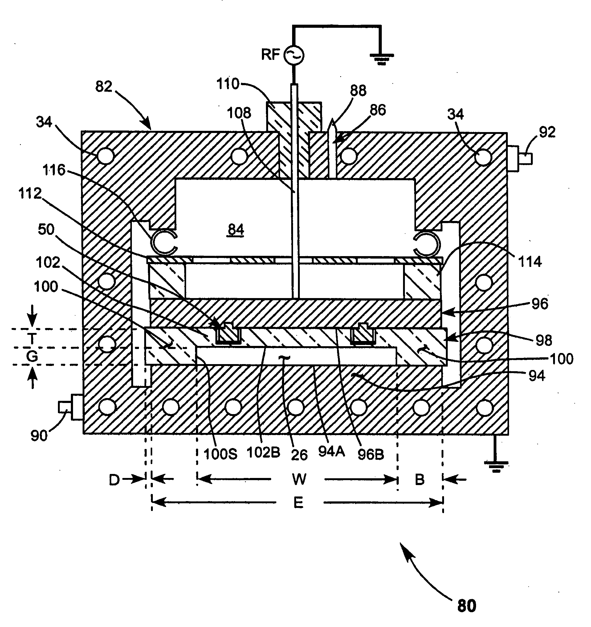
[0039]FIG. 4 is a cross-section view schematically illustrating an embodiment 80 of a slab CO2 laser in accordance with the present invention integrated into a metal enclosure 82. FIG. 5 is three-dimensional view schematically illustrating laser 80 with enclosure 82 partially cut away. Enclosure 82 is preferably formed from extruded aluminum components and is electrically connected to ground potential. Interior 84 of enclosure 82 is filled with a lasing gas via a port 86, the tip 88 of which can be sealed off, to seal enclosure 82 once lasing-gas filling is complete. Cooling channels 34 are provided in the base, sidewalls, and top of enclosure 82. Cooling fluid is directed into the channels via an inlet port 90 and exits the channels via an outlet port 92.

[0040] A raised base-portion 94 of enclosure 82 forms a ground electrode for slab laser 80. Electrode 94 has a width E. A separate top or “hot” electrode 96 is spaced apart from ground electrode 94 by a ceramic slab 98 having raise...

embodiment 130

[0047]FIG. 8 schematically illustrates an embodiment 130 of a slab CO2 laser in accordance with the present invention. Laser 130 is similar to laser 90 of FIG. 7 with an exception that in addition to a ceramic slab 120 in contact with electrode 94, there is a similar ceramic slab 121 in contact with hot electrode 96. In laser 90, discharge gap 26 is formed between lower surface 121B of ceramic slab 121 and upper surface 120A of ceramic slab 120.

[0048] One disadvantage of including two dielectric slabs and forming the discharge gap between those slabs is that laser output will not be plane polarized as would be the case in embodiments of the inventive laser wherein the discharge gap is formed between a dielectric slab and a metal electrode. If a polarized output is required a separate polarizer (not shown in FIG. 8) should be included in resonator 36.

embodiment 140

[0049] Another further embodiment 140 of a slab laser in accordance with the present invention is schematically illustrated in FIG. 9. Laser 140 is similar to laser 60 of FIG. 2 with an exception that ceramic slab 21 of laser 60 is replaced with a slab 142 that is held in contact with hot electrode 12. Slab 142 is wider than electrode 12, such that an edge portion 142E of the slab extends laterally beyond the electrode for reasons discussed above. Detail of the holding arrangement is depicted in FIG. 9A. Here a bolt 144, having a head 146 and a post 148, has head 146 thereof bonded via a solder bond 152 to metal pad 150 that is deposited on slab 142. A plurality of such bonded bolts, here four, are disposed along the length of slab 142. The bolts extend through holes (not shown) in electrode 12. Nuts 154 and spring washers 156 are attached to the posts to hold the ceramic slab in contact with the electrode (see FIG. 9). The spring washers accommodate relative difference in expansion...


PUM


Abstract

A slab laser includes two elongated electrodes arranged spaced apart and face-to-face. Either one or two slabs of a solid dielectric material extend along the length of the electrodes between the electrodes. A discharge gap is formed either between one of the electrodes and one dielectric slab, or between two dielectric slabs. The discharge gap is filled with lasing gas. A pair of mirrors is configured and arranged to define a laser resonator extending through the gap. An RF potential is applied across the electrodes creating a gas discharge in the gap, and causing laser radiation to circulate in the resonator. Inserting dielectric material between the electrodes increases the resistance-capacitance (RC) time constant of the discharge structure compared with the RC time constant in the absence of dielectric material. This hinders the formation of arcs in the discharge, which enables the laser to operate with higher excitation power, higher lasing gas pressure, and higher output power than would be possible without the dielectric inserts.

Description

TECHNICAL FIELD OF THE INVENTION [0001] The present invention relates generally to carbon dioxide (CO2) slab lasers. The invention relates in particular to a slab laser having a dielectric coupling-element between metal slab electrodes. DISCUSSION OF BACKGROUND ART [0002] CO2 lasers are commonly used in commercial manufacturing for operations such as cutting or drilling, in particular, in nonmetallic materials. One form of CO2 laser suited for such operations is known to practitioners of the art as a “slab” laser. Such a laser has an assembly including a pair of elongated, slab-like planar electrodes arranged face-to-face and spaced apart to define a gap between the electrodes. The electrodes are usually contained in a gas tight enclosure. The enclosure and the gap between the electrodes are filled with a lasing gas mixture including CO2. A radio frequency (RF) potential is applied across the electrodes to cause an electrical discharge in the CO2 laser gas mixture. The discharge ene...

Claims


Application Information

Patent Timeline
IPC IPC(8): H01S3/22
CPCH01S3/0315H01S3/0388H01S3/0407H01S3/2232H01S3/09705H01S3/0971H01S3/041
Inventor SHACKLETON, CHRISTIAN J.GARDNER, PHILLIP J.DEMARIA, ANTHONY J.SEGUIN, VERNONKENNEDY, JOHN T.
Owner COHERENT INC
Why Eureka
Try Eureka