
Axial flow pump and diagonal flow pump

a technology of axial flow and diagonal flow, which is applied in the direction of machines/engines, stators, liquid fuel engines, etc., can solve the problems of choking up of flow paths due to separation vortex, reducing pump performance, and worsening of total performance of the pump, so as to reduce the pump performance and improve the overall performance of the pump. , the effect of reducing the pump performan

Inactive Publication Date: 2006-02-09
HITACHI LTD +1
View PDF4 Cites 16 Cited by
  • Summary
  • Abstract
  • Description
  • Claims
  • Application Information

AI Technical Summary

Benefits of technology

[0006] The purpose of the present invention is to minimize the degradation of the performance due to the separation vortex generated at the leading edges of guide vanes by means of flow volume changes and to provide an axial flow pumps and diagonal flow pumps that can maintain high performance in the wide range of operation condition from a small flow volume to a large flow volume.

Problems solved by technology

Since this vortexes choke up the flow paths generated between any adjacent two guide vanes axially set around and work as a resistance against the flow so that the total performance of the pump becomes worse.
The direction of the flow are deviated in the reverse direction against the direction of the flow in case when the flow volume is small and therefore the separation is generated at the leading edges of the guide vanes in a reverse side so that the vortexes of the separation choke the flow paths up and reduce the pump performance.
The separation distance between adjacent guide vanes in the cross sectional plane is shorter in the region close to the hub and longer in the region close to the shroud due to the smaller radius the region closer to the hub and therefore the effect of choking up of flow paths due to the existence of the separation vortex is particularly a serious problem.

Method used


Image

  • Axial flow pump and diagonal flow pump
  • Axial flow pump and diagonal flow pump
  • Axial flow pump and diagonal flow pump

Examples


Embodiment Construction

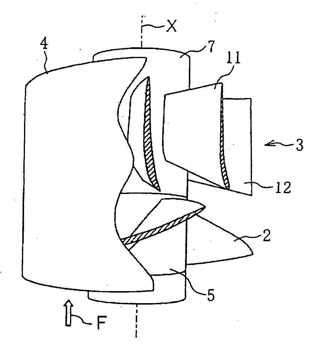
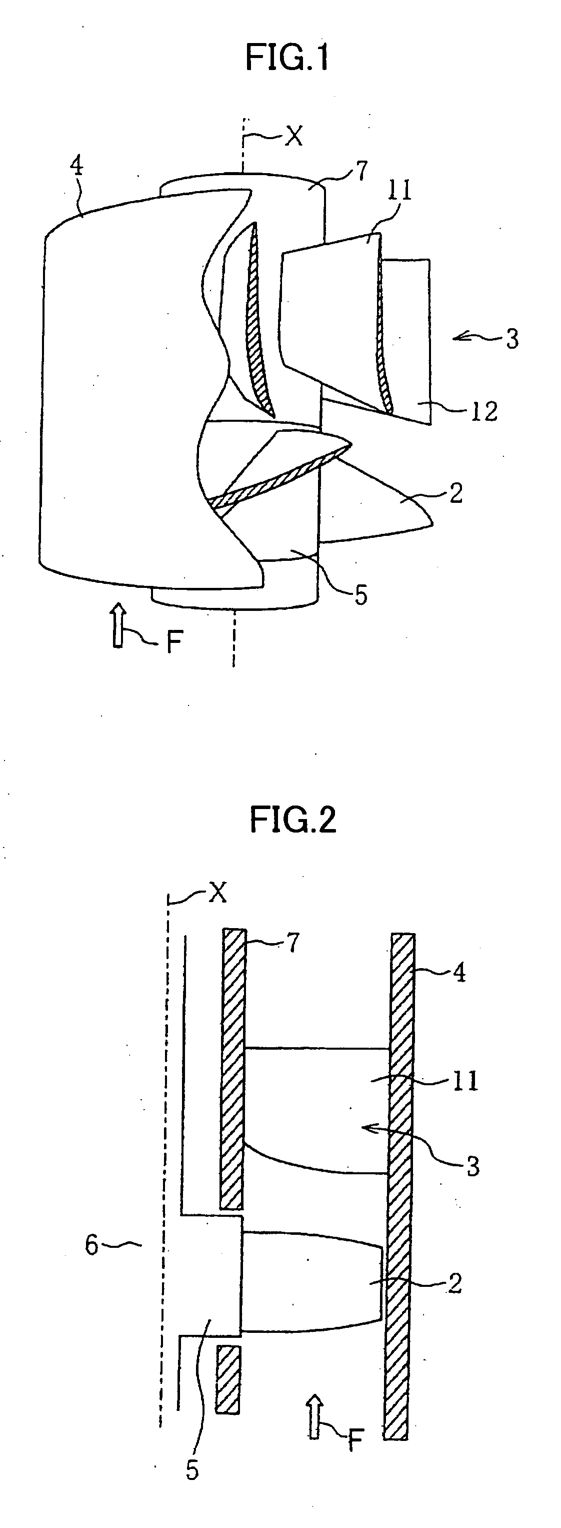
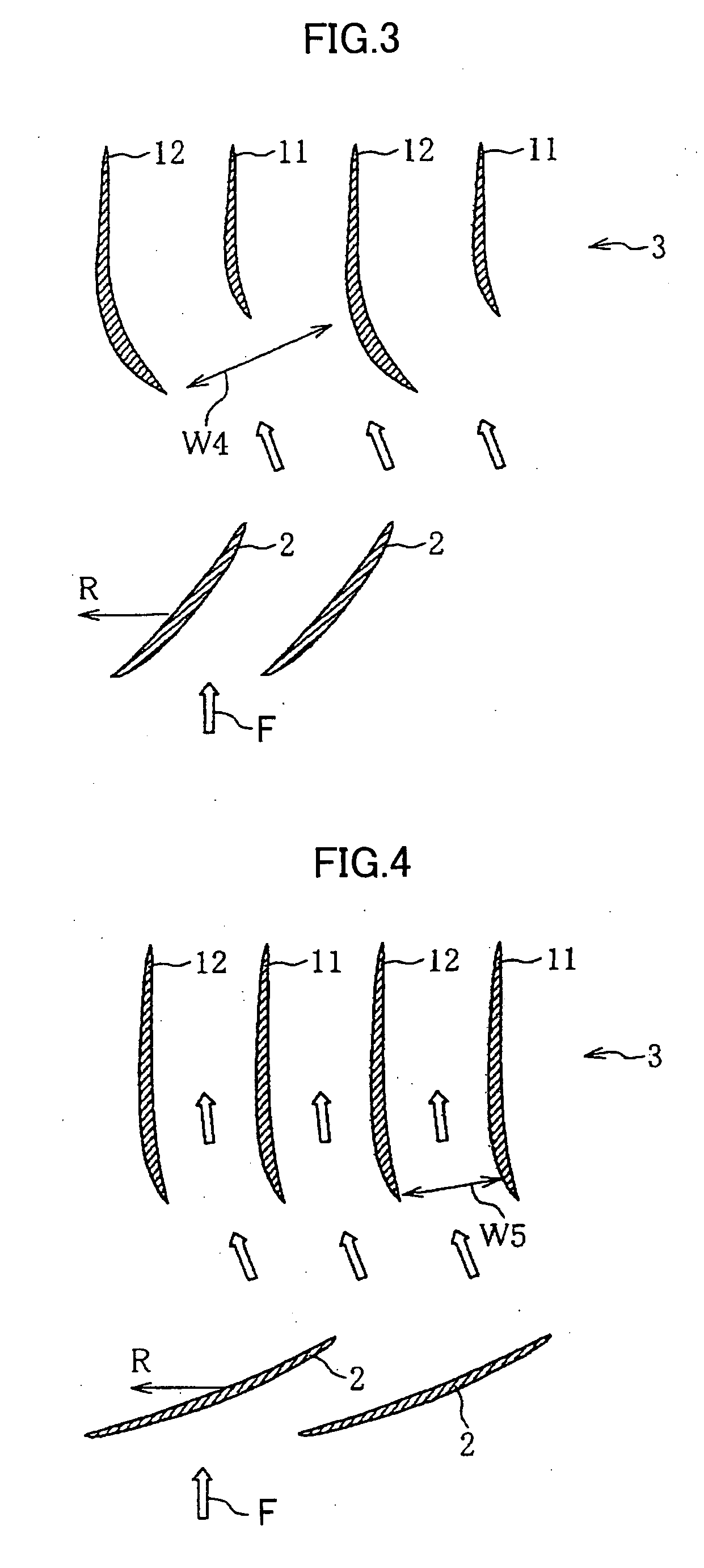
[0023] (1) In order to achieve the above purpose, the present invention provides an axial pump wherein a plurality of some of guide vanes is set in the back flow of the plurality of impellers and the leading edges of the part of the guide vanes are placed in the downstream regarding to the pump rotation axis direction so that the plurality of the vanes which have different shapes from those of the other vanes are placed around the angular direction.

[0024] A plurality of some of guide vanes is set in the downstream of the plurality of the impellers and the area of the inlet to flow path to guide vanes becomes large. Since the effective area of the inlet to the flow path to guide vanes becomes large in the operation conditions other than the optimum condition, the performance degradation due to the separation vortexes generated at the leading edges of the guide vanes can be minimized and the high performance pump covering the wide range of operation condition from the small flow volu...


PUM


Abstract

The guide vanes comprise two kinds of guide vanes which are alternatively placed around the angular direction. One kind of the guide vanes have longer length than the other kinds of the guide vanes at the region which is close to the surface of hub but have substantially same lengths the other kind of the guide vanes at the region which is close to the shroud. The leading edges of the second kind of guide vane locate in the further downstream of the pump axial direction than the fist kind of guide vanes.

Description

FIELD OF INVENTION [0001] The present invention relates to an axial flow pump and a diagonal flow pump, especially, those that have plural impellers and plural guide vanes placed in the back stream of the impellers. [0002] Axial-flow pumps generate rotational energy in the fluid by means of the impellers thereof and convert the rotational energy to the static pressure by means of guide vanes placed in the back flow of the impellers. Usually, the impellers and the guide vanes have the same physical shape of vanes and are mounted to the axis and / or the casing in uniformly same separation. The flow at the outlet of the impellers has a flow component along a rotational axis and an angular component which is called as a rotational component, hereinafter. The guide vanes are mounted in such a configuration that the leading edges of the vanes are compliant to the axial angle of the rotational component of the back flow generated by the impellers. Since the flow condition of the fluid flow ...

Claims


Application Information

Patent Timeline
Patent Type & Authority Applications(United States)
IPC IPC(8): F01D9/00
CPCF04D29/548F04D29/542F04D29/544
Inventor ISHII, TAKANORIIWANO, RYUICHIROMANABE, AKIRAINOUE, YASUHIRO
Owner HITACHI LTD
Learn More