Multi-ply wrap label

a label and multi-ply technology, applied in the field of labels, can solve the problems of increasing the chance of misalignment, buckling, or machine jamming during the application process, and the design of the prior art’s “wrap around” design has several limitations relating to machine application to containers, etc., to achieve the effect of shortening the length, less “flimsy” and improving press efficiencies

Active Publication Date: 2006-02-09
WS PACKAGING GROUP
View PDF7 Cites 21 Cited by
  • Summary
  • Abstract
  • Description
  • Claims
  • Application Information

AI Technical Summary

Benefits of technology

[0025] Advantages of the multi-ply wrap label of this invention are numerous. Firstly, the present invention provides a base ply and upper ply with available print area that is of shorter length as compared to a typical “wrap around” label with similar total available print area. Secondly, the present invention with its two plies of material is less “flimsy” than a typical single ply “wrap around” label and will be less likely to misfeed during machine label application. Thirdly, the shorter format of this invention as compared to a typical “wrap around” label can translate to improved press efficiencies (less total run footage processed per label). Fourthly, the upper ply and base ply can be of differing materials resulting in a single strip (after application) having two different materials. Fifthly, the use of an upper ply extending past the base ply as a “single layer” enables this invention to be applied to tight radius containers while lessening or eliminating the possibility of wrinkling or buckling as would occur with a typical “multi-ply” label with similar print areas. Sixthly, this invention teaches a shear type splice with significantly more strength than a peel type hinge as seen on current “multi-ply” labels, such as illustrated in FIG. 2.

Problems solved by technology

As such, the “wrap around” designs of prior art have several limitations relating to machine application to containers such as round bottles.
First, the relatively expansive length of the “wrap around” label in comparison to the container circumference often results in the need for expensive, specially modified labeling equipment to apply multiple wraps of label material.
The extra length of a “wrap around” label as compared to a standard pressure sensitive label increases the opportunity of misalignment, buckling, or machine jamming during the application process.
Secondly, the combination of the “wrap around” label being extra long and also being comprised of only a single ply of paper or plastic renders the label “flimsy” and more likely to misfeed or jam during the application process.
Thirdly, the extra long nature of the “wrap around” label as compared to a “multi-ply” label with similar available surface area for printing text and graphics translates to comparatively longer production time.
An additional limitation of current “wrap around” label designs is that as the long, single ply label is applied around a container in wrap fashion, it is now seen as “multilayer” label (one wrap on top of another wrap) with all “layers” being composed of the same label material.
When such labels are applied to curved or non-planar surfaces such as a cylindrical bottle or squeeze tube, the results can be unsatisfactory.
An additional limitation with current “multi-ply” labels relates to the relatively weak bonding strength of the hinge which holds the upper ply to the base label when said label is in an open configuration as would be the case if being opened and viewed by an end user.
This can render the label unfit for use, and may even violate governmental labeling laws.

Method used


Image

  • Multi-ply wrap label
  • Multi-ply wrap label
  • Multi-ply wrap label

Examples


first embodiment

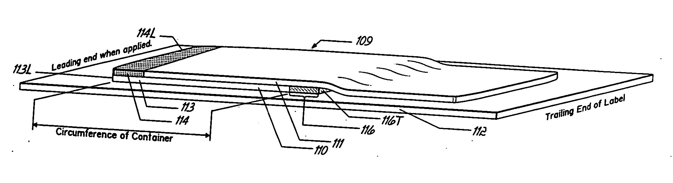
[0073] With reference to FIGS. 3-8 and their counterparts, a label according a first embodiment of the present invention, generally denoted by the numeral 109, is shown therein. Label 109 includes a base ply 110, and an upper ply 111. A base ply leading end portion is shown as numeral 113 and an upper ply leading end portion is shown as numeral 114, each having a leading edge 113L and 114L respectively. The first embodiment has both said ply leading end portions being coextensive at their said leading edges prior to application.

[0074] The upper ply 111 is shown in FIGS. 3-5 as being longer than the base ply 110, although said upper ply could also be equal to or shorter than said base ply 110 as is illustrated in FIGS. 8a-8f.

[0075] Referring to FIGS. 5a-5b, which illustrate features of the label 109, base ply 110 is coated on its lower surface with a pressure sensitive adhesive 118 and the upper ply 111 is also coated with a pressure sensitive adhesive 119 on its lower surface. Lab...

second embodiment

[0093] With reference to FIGS. 9a-9d, a label according a second embodiment of the present invention, generally denoted by the numeral 209, is shown therein. Label 209 includes a base ply 210, and an upper ply 211. As in the first embodiment the entire length of the upper ply 211 could be longer than, equal to, or shorter than base ply 210.

[0094] Unlike the first embodiment, a feature of the second embodiment has the upper ply leading end portion 214 of label 209 as not being coextensive with the base ply leading end portion 213 prior to application. Specifically, all labels of the second embodiment feature the upper ply leading edge 214L extending forward, past the base ply leading edge 213L. As such, during machine application to a container such as a round bottle 2, the upper ply leading end portion 214 will become affixed to said bottle prior to the base ply 210 being affixed.

[0095] The end result, after application to the bottle 2, is that the end-splice 215 will be partially...

third embodiment

[0099] With reference to FIGS. 10a-10d, a label according a third embodiment of the present invention, generally denoted by the numeral 309, is shown therein. Label 309 includes a base ply 310, and an upper ply 311. As in the first and second embodiments the entire length of the upper ply 311 could be longer than, equal to, or shorter than base ply 310.

[0100] Unlike the first and second embodiments, the third embodiment features the upper ply leading edge 314L of label 309 as being recessed in relation to the base ply leading edge 313L prior to application as illustrated in FIG. 10a. As such, during machine application to a container such as a round bottle 2, the base ply 310 will become adhesively affixed to bottle 2 with a full 360°“wrap” and continue to wrap on itself for a distance more. Eventually during the application process, the base ply 310, with adhesive on its underside, will encounter and superimpose (overlap) its trailing end portion 316 over the upper ply leading end...


PUM

PropertyMeasurementUnit
adhesionaaaaaaaaaa
pressureaaaaaaaaaa
pressure sensitiveaaaaaaaaaa

Abstract

A multi-ply, expanded content wrap label includes a base ply and an upper ply thereon with adhesive applied to the underside of a trailing end of the base ply to form a splice between the base ply and the upper side of the upper ply when the label is applied to a container.

Description

FIELD OF THE INVENTION [0001] Applicant claims the benefit of the priority dates of: U.S. Provisional Patent Application Ser. No. 60 / 599,925, filed Aug. 9, 2004 and of U.S. Provisional Patent Application Ser. No. 60 / 672,472 filed Apr. 18, 2005, each of which is herein expressly incorporated by reference for priority disclosure and background purposes. The following specification claims and drawings supercede any inconsistency with said provisional patent applications. [0002] This invention relates to labels and more particularly, extended or expanded content labels for use on containers, for example. BACKGROUND OF THE INVENTION [0003] The packaging industry has long had an interest in the manufacture and use of specially designed labels as a means of increasing available graphic and text area where use of a common single ply label affixed to a container would lack such extra print space. The demand for increased label print space arises from governmental labeling laws, need for mult...

Claims


Application Information

Patent Timeline
Patent Type & Authority Applications(United States)
IPC IPC(8): B32B33/00
CPCB65C3/163B65C9/1869G09F3/10Y10T428/2848Y10T156/1077Y10T428/1495Y10T428/14Y10T428/149Y10T428/1476Y10T156/1074Y10T428/28
Inventor MATTHEWS, LOWELL F.PUTZIER, KYLE J.WIENER, CRAIG JOHNPAGE, JOSEPH CARLOS
Owner WS PACKAGING GROUP
Why Eureka
Try Eureka