
Process and system for laser crystallization processing of film regions on a substrate to minimize edge areas, and a structure of such film regions

a laser crystallization and processing system technology, applied in lasers, transistors, manufacturing tools, etc., can solve the problems of non-uniform edge region, fabricated thin-film transistor (“tft”) devices, and often suffer from microstructural non-uniformities, so as to increase the speed of processing the semiconductor film

Inactive Publication Date: 2006-02-09
THE TRUSTEES OF COLUMBIA UNIV IN THE CITY OF NEW YORK
View PDF99 Cites 83 Cited by
  • Summary
  • Abstract
  • Description
  • Claims
  • Application Information

AI Technical Summary

Benefits of technology

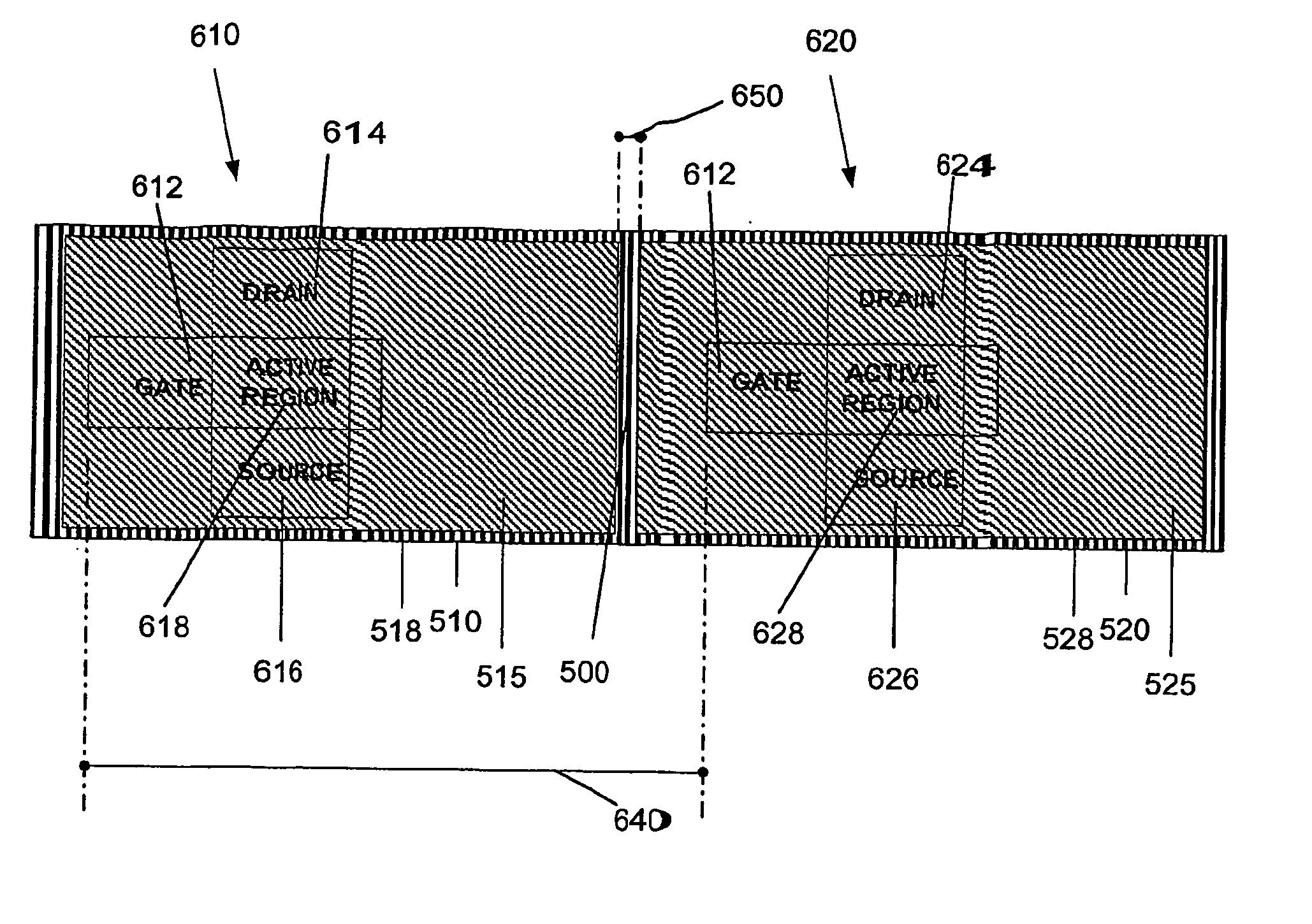
[0010] Therefore, one of the objects of the present invention is to provide an improved process and system which can make the edge regions of the crystallized areas of the semiconductor thin film relatively small (e.g., one such region can be smaller than the distance between the adjacent TFT devices). Thus, it is possible to place the active regions of the TFT devices on the semiconductor thin film away from these edge regions. Another object of the present invention is to increase the speed to process the semiconductor films for their use with the liquid crystal displays and / or organic light emitting diode displays. Still an-other object of the present is to have a capability for utilizing various fluences of the beam pulse for irradiating the areas of the semiconductor thin film, so long as such fluence induces a crystallization of the irradiated areas of the semiconductor thin film.
[0011] In accordance with at least some of these objectives as well as others that will become apparent with reference to the following specification, it has now been determined that the reduction the size of the edge regions of the irradiated and crystallized areas of the semiconductor thin film is advantageous to, reduce the edge effect. It was also ascertained that the grains provided in the edge regions of such areas are different from the grains of the areas that are arrangement, e.g., between two oppositely-spaced edge regions of the semiconductor thin film. Further, it was determined that the use of the two-dimensional mask to pass the beam pulse there through configured the profile of the resultant masked beam pulse to be well defined, thus decreasing or eliminating the portion of the beam pulse which may have a gradually-reducing fluence level that may cause the undesired edge effect.

Problems solved by technology

However, the semiconductor films processed using such known ELA methods often suffer from microstructural non-uniformities such as edge effects, which manifest themselves in availing a non-uniform performance of thin-film transistor (“TFT”) devices fabricated on such films.
Such non-uniformity in edge regions is particularly problematic in that the visual transitions between the neighboring pixels corresponding to the irradiated and crystallized areas of the semiconductor thin film on the liquid crystal displays (“LCDs”) or organic light emitting diode displays are not as smooth as could be desired, and may even be visible in certain cases, which is undesired.
This is also because the edge effects promote a low performance in TFT devices whose active regions are provided thereon.
However, details of previous approaches make it impossible to completely eliminate the non-uniformities that are introduced from the edge areas (which are typically between 100 μm to 1,000 μm or higher).
Thus, the cross sectional area of the portions of the semiconductor thin film on which the TFT devices could be placed would be significantly reduced due to such disadvantageous edge effects causing large non-uniform edge areas which border these portions.
The edge regions are known to be disadvantageous for placing the TFT devices (and especially their active regions) thereon.
However, such conventional procedure would require multiple irradiation by the beam pulses of the same areas, and the processing of the semiconductor film would be somewhat slow.

Method used


Image

  • Process and system for laser crystallization processing of film regions on a substrate to minimize edge areas, and a structure of such film regions
  • Process and system for laser crystallization processing of film regions on a substrate to minimize edge areas, and a structure of such film regions
  • Process and system for laser crystallization processing of film regions on a substrate to minimize edge areas, and a structure of such film regions

Examples


second embodiment

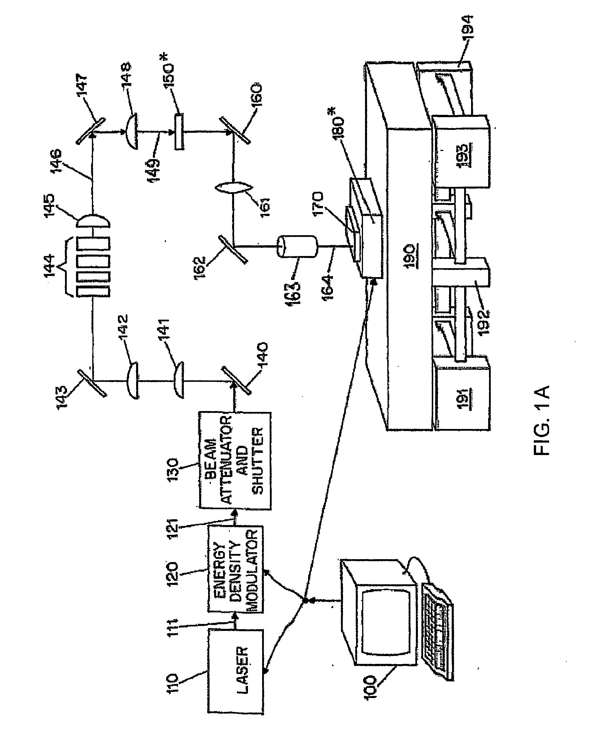
[0058]FIGS. 6A-6D show an exemplary progression of the process according to the present invention in which a plurality of successive areas along the first conceptual column 205 of the semiconductor thin film 175 is irradiated by the masked beam pulse 164 (comprised of beamlets) which is shaped by the mask 150′ of FIG. 5A. The translation of the sample 170 with respect to the impingement thereof by the beam pulse 164 is substantially the same as the translation described above with reference to FIGS. 4A-4F. The difference between the irradiation of the areas 310, 320, . . . , 380, 390, 410, 420 by the beam pulse 164 shaped by the mask 150 of FIG. 3 and the areas 460, 470 by the beam pulse 164 shaped by the mask 150′ is that substantially the entire areas 310, 320, . . . , 380, 390, 410, 420 are irradiated and crystallized, as opposed to only certain small portions 462 of the areas 460, 470 are irradiated and crystallized.

[0059] Similarly to the area 310 in FIG. 4A, the portions 462 o...

third embodiment

[0060] In addition, it is possible to utilize a mask 150″according to the present invention as shown in FIG. 7 which has a long and narrow open or transparent region 490 so as to pattern and shape the beam 149 into the beam pulse 164. For example, the length of the region 490 can be 0.5 cm and the width thereof may be 0.1 mm. In this manner, each conceptual column of the sample 170 illustrated in FIG. 2 can be irradiated by the beam pulse 164 shaped by this mask 150″. In addition, it may be possible for the length of the region 490 to be 30 cm. Thus, instead of subdividing the semiconductor thin film 175 into a number of conceptual columns, and irradiating each column separately, it is possible to irradiate and crystallize selected portions of the semiconductor thin film 175 by translating the sample 170 in the −Y direction from one edge of the sample 170 to the opposite edge thereof. It is important that the center regions be formed using such processing technique such that it woul...


PUM

PropertyMeasurementUnit
lengthaaaaaaaaaa
lengthaaaaaaaaaa
areasaaaaaaaaaa

Abstract

A process and system for processing a thin film sample are provided. In particular, a beam generator can be controlled to emit at least one beam pulse. The beam pulse is then masked to produce at least one masked beam pulse, which is used to irradiate at least one portion of the thin film sample. With the at least one masked beam pulse, the portion of the film sample is irradiated with sufficient intensity for such portion to later crystallize. This portion of the film sample is allowed to crystallize so as to be composed of a first area and a second area. Upon the crystallization thereof, the first area includes a first set of grains, and the second area includes a second set of grains whose at least one characteristic is different from at least one characteristic of the second set of grains. The first area surrounds the second area, and is configured to allow an active region of a thin-film transistor (“TFT”) to be provided at a distance therefrom.

Description

RELATED APPLICATION [0001] This application claims priority to U.S. Provisional Application No. 60 / 405,085, which was filed on Aug. 19, 2002, and is incorporated by reference.NOTICE OF GOVERNMENT RIGHTS [0002] The U.S. Government may have certain rights in this invention pursuant to the terms of the Defense Advanced Research Project Agency award number N66001-98-1-8913.FIELD OF THE INVENTION [0003] The present invention relates to techniques for processing of thin films, and more particularly to techniques for processing semiconductor thin films to reduce non-uniform edge areas of the crystallized regions of the thin film so that at least an active region of an electronic devices, such as a thin-film transistor (“TFT”), can be placed away from such non-uniform edge areas. BACKGROUND OF THE INVENTION [0004] Semiconductor films, such as silicon films, are known to be used for providing pixels for liquid crystal display devices and organic light emitting diode displays. Such films have...

Claims


Application Information

Patent Timeline
Patent Type & Authority Applications(United States)
IPC IPC(8): H01L21/20H01L21/84H01L21/324H01L21/26H01L21/336H01L21/77H01L29/04H01L29/786
CPCB23K26/063B23K26/0656H01L21/2026H01L21/268H01L29/78651H01L27/1296H01L29/04H01L29/66742H01L27/1285B23K26/0622B23K26/066H01L21/02683H01L21/02686H01L21/02422H01L21/02678H01L21/02488H01L21/02532H01L21/02689H01L21/02691H01L21/26H01S3/10
Inventor IM, JAMES S.
Owner THE TRUSTEES OF COLUMBIA UNIV IN THE CITY OF NEW YORK
Learn More