Clutch driven reaction wheel steering unit

a technology of steering unit and reaction wheel, which is applied in the direction of cosmonautic components, cosmonautic parts, cosmonautic vehicles, etc., can solve the problems of limited bandwidth and limited capability of designs, and the bandwidth of devices is also substantially infinite, so as to reduce device complexity, limited bandwidth, and limited capability

Inactive Publication Date: 2006-02-16
UNIVERSITY OF NORTH TEXAS
View PDF3 Cites 18 Cited by
  • Summary
  • Abstract
  • Description
  • Claims
  • Application Information

AI Technical Summary

Benefits of technology

[0007] The objective of the present invention is to address the shortcomings of conventional designs. Most of the existing designs rely on a series of stepper motors or jack screws to affect desired changes in momentum. Current mechanisms use motor speed to vary momentum, or a jack screw to change the axis of rotation to affect the momentum of the attached flywheel. As a result, these designs have limited bandwidth and limited capability. The present invention uses a single drive motor providing momentum for all three axes in a single unit. The use of a single motor reduces device complexity and simplifies device control. In addition, most conventional designs require a separate mechanism for each axis that is to be controlled. The present invention is adapted to control all three axes of rotation in a single unit.

Problems solved by technology

As a result, these designs have limited bandwidth and limited capability.
In addition, because the speed of the motor remains substantially constant, the resulting bandwidth of the device is also substantially infinite.

Method used


Image

  • Clutch driven reaction wheel steering unit
  • Clutch driven reaction wheel steering unit
  • Clutch driven reaction wheel steering unit

Examples


Embodiment Construction

[0015] While an exemplary embodiment of the present invention is discussed in detail below, it should be appreciated that the present invention provides many applicable inventive concepts which can be embodied in a wide variety of specific contexts

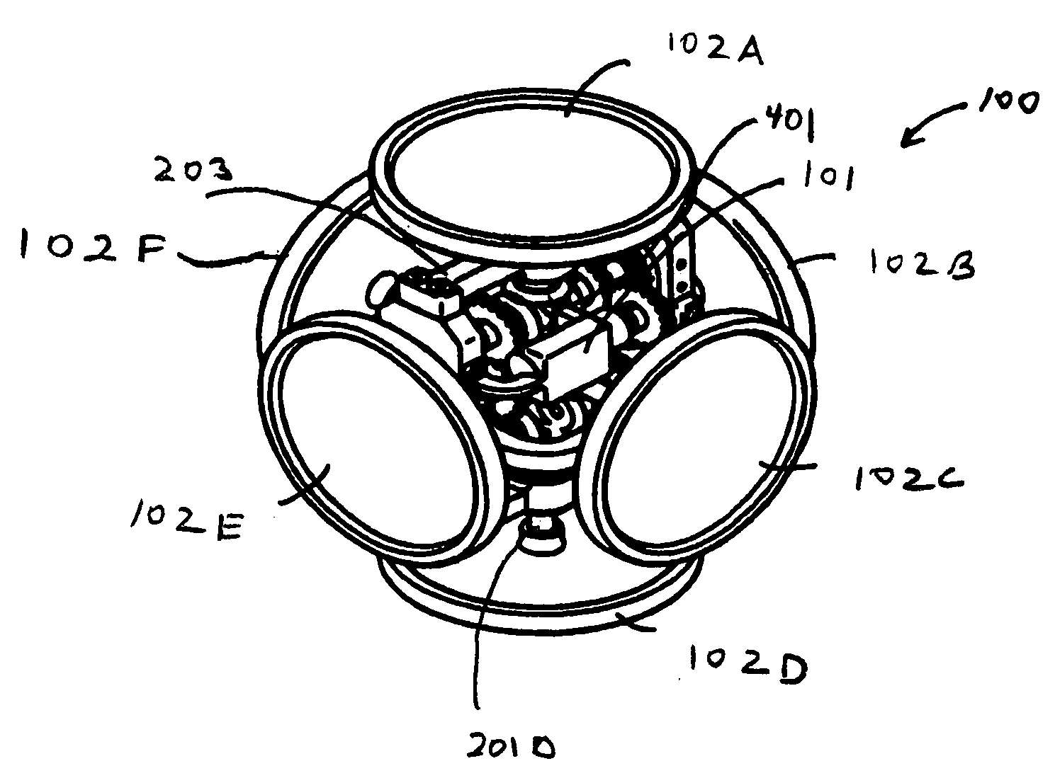
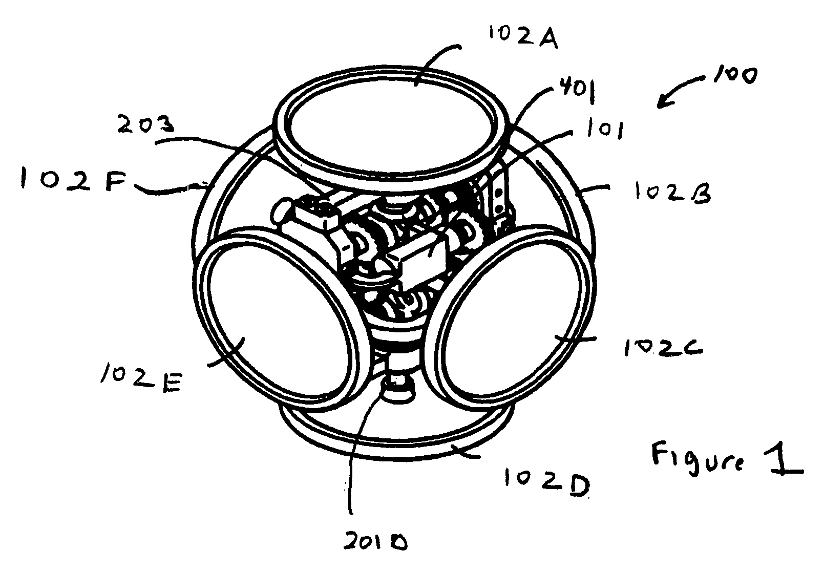
[0016]FIG. 1 provides an isometric view of the present invention showing assembly 100 including drive motor 101. Also seen are six flywheels 102A, 102B, 102C, 102D, 102E and 102F, operable to turn the unit through all three axes of rotation. More generally, the clutch driven reaction wheel steering unit comprises a unit frame 203, the drive motor 101 being mounted within or supported by the unit frame 203. A motor unit shaft extends out from the drive motor 101. A motor unit gear is coupled to an end of the extended drive motor shaft. A plurality of gears, including miter gears, are coupled directly or indirectly to the drive motor gear. A first plurality of shafts are coupled to the plurality of gears and mounted within and through, or s...


PUM


Abstract

What is disclosed is a clutch driven reaction wheel steering unit having at least a single drive motor (101) coupled indirectly to a plurality of flywheels operable to provide momentum for all three axes in a single unit. In an exemplary embodiment, the drive motor (101) is mounted within a unit frame (203). A plurality of gears, including miter gears, are coupled directly or indirectly to the drive motor (101). Six flywheels (102A, 102B, 102C, 102D, 102E and 102F) are coupled to the ends of a plurality of shafts which extend through or are supported by the unit frame (203). Clutches are operable to selectively transmit rotational motion to the second plurality of shafts.

Description

CLAIM OF PRIORITY [0001] This application claims priority to U.S. Provisional Patent Application Ser. No. 60 / 559,893, filed Apr. 6, 2004, entitled “Clutch Driven Reaction Wheel Steering Unit,” the entire contents of which are incorporated herein by this referenceSTATEMENT REGARDING FEDERALLY SPONSORED RESEARCH OR DEVELOPMENT [0002] No federal grants or funds were used in the development of the present invention. FIELD OF THE INVENTION [0003] The present invention relates to a system for vehicle stabilization and attitude control and, more particularly, to a flywheel based system for these purposes. BACKGROUND OF THE INVENTION [0004] The ability to stabilize a vehicle, particularly spacecraft in orbit and to reposition it as necessary is of great importance. Without this capability, most satellites and missile systems would not function properly. There have been a variety of systems developed to provide vehicle attitude control, with the majority using some form of gyroscopic device....

Claims


Application Information

Patent Timeline
Patent Type & Authority Applications(United States)
IPC IPC(8): B64G1/28
CPCB64G1/286B64G1/283
Inventor SMITH, MONTYMAESTAS, JEFFERY E.
Owner UNIVERSITY OF NORTH TEXAS
Why Eureka
Try Eureka