Radiation detecting apparatus, scintillator panel, and radiographing system

a technology of scintillator and phosphor protective layer, which is applied in the direction of instruments, radiation measurement, measurement devices, etc., can solve the problems of slow film forming speed of phosphor protective layer, inconvenient operation, and disturbance of inherent light propagation, so as to reduce the cost of the product, reduce the number of working steps, and simplify the manufacturing steps

Active Publication Date: 2006-02-16
CANON KK
View PDF9 Cites 52 Cited by
  • Summary
  • Abstract
  • Description
  • Claims
  • Application Information

AI Technical Summary

Benefits of technology

[0020] According to the invention, a moisture-proofing effect for the penetration of the moisture from an interface between the phosphor layer and the substrate on the side of the side surface of the substrate can be improved.
[002

Problems solved by technology

However, since the phosphor layer having the columnar crystalline structure is a hygroscopic material, there is such a problem that if it absorbs the moisture, the crystal deliquesces and the columnar crystals are joined with each other, so that the inherent light propagation is disturbed and the resolution is remarkably deteriorated.
However, since the phosphor protective layer using the organic film made of polyparaxylilene as disclosed in the foregoing related art is formed by the CVD method, a film forming speed of the phosphor protective layer is equal to about 100 to 2000 Å/min and slow.
Therefore, a time of 2000 to 100 minutes is necessary as a film forming time to form the phosphor protective layer of 20 μm and there is such a problem that the mass productivity is low.
Further, since there are disadvantages in terms of the number of st

Method used


Image

  • Radiation detecting apparatus, scintillator panel, and radiographing system
  • Radiation detecting apparatus, scintillator panel, and radiographing system
  • Radiation detecting apparatus, scintillator panel, and radiographing system

Examples


first embodiment

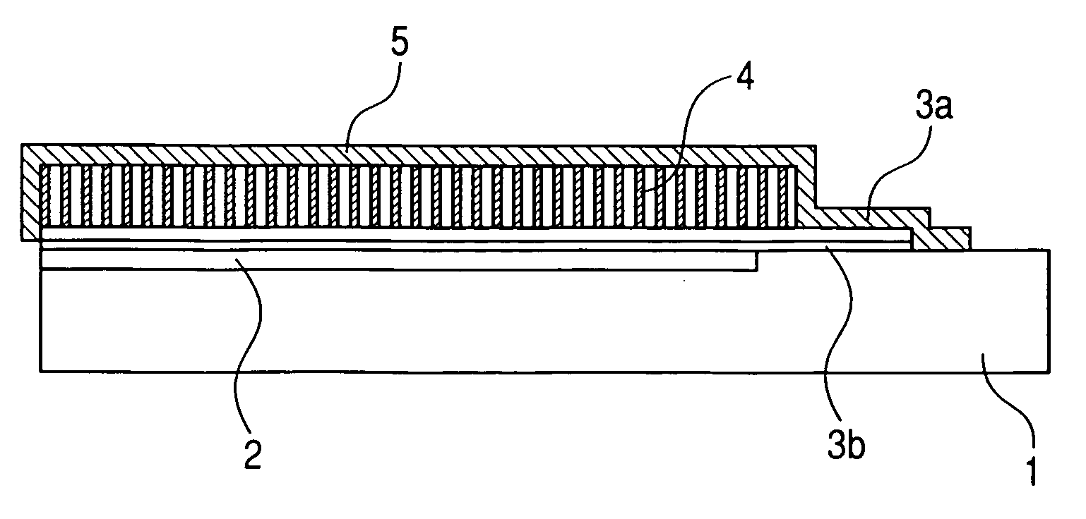
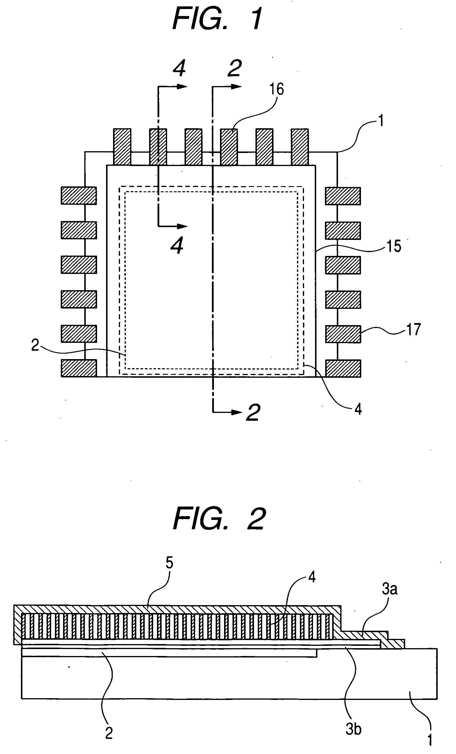
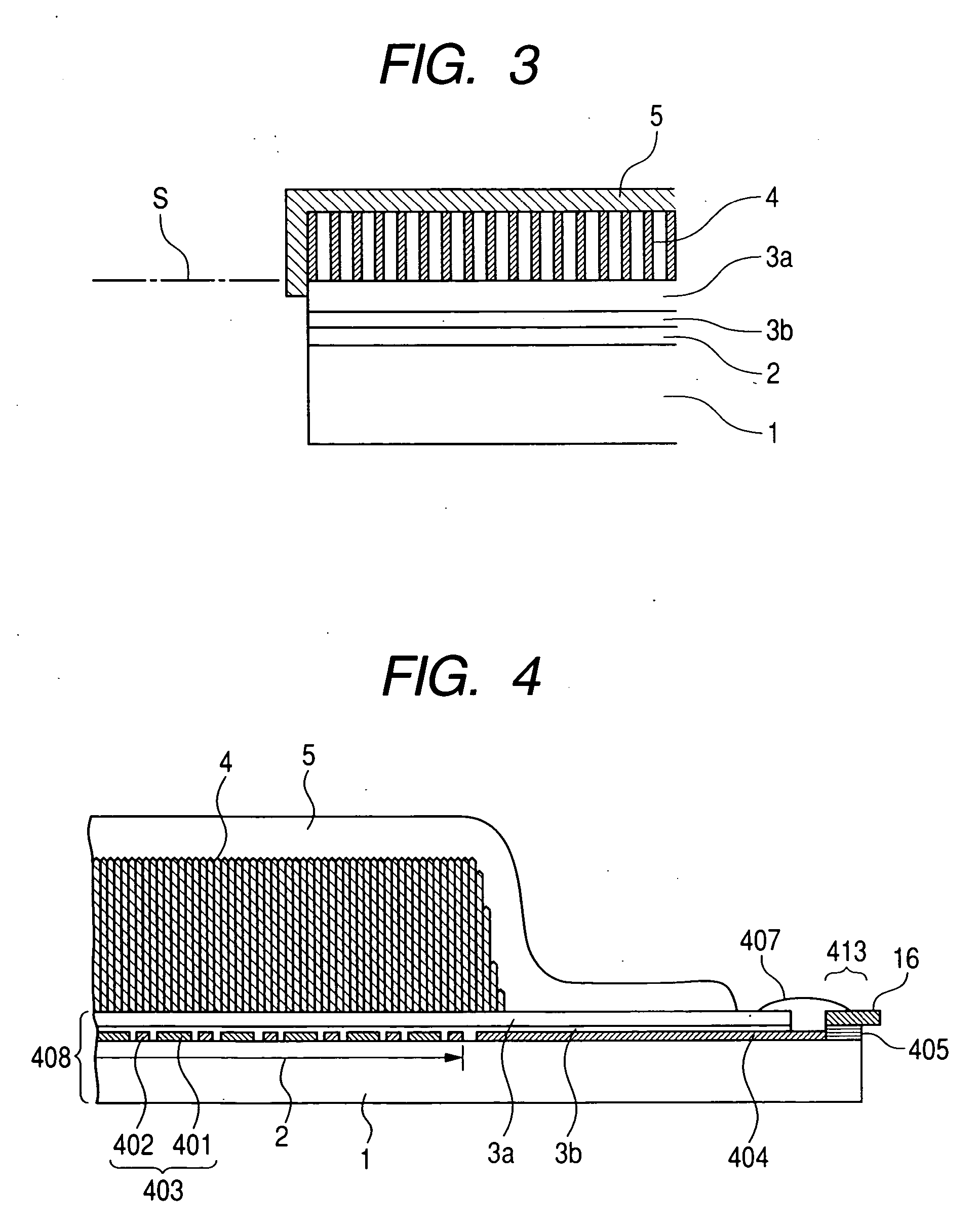
[0055]FIG. 1 is a schematic plan view of the radiation detecting apparatus of the direct evaporation deposition type according to the first embodiment of the invention. FIG. 2 is a cross sectional view taken along the line 2-2 in FIG. 1. FIG. 3 is a partially enlarged diagram of FIG. 2. FIG. 4 is a cross sectional view taken along the line 4-4 in FIG. 1. In FIGS. 1 to 4, reference numeral 1 denotes a substrate such as glass or the like; 401 photoelectric conversion elements; and 402 wirings. A photoreceiving unit 403 is constructed by the photoelectric conversion elements 401, the wirings 402, and thin film transistors (TFTs). Reference numeral 404 denotes an electrical connecting unit (lead-out wiring); 3b a sensor protective layer; 3a a phosphor underlying layer; and 405 a wiring connecting unit. A photodetector (sensor panel) 408 is constructed by the component elements 1, 401, 402, 404, 3b, 3a, and 405. A connecting unit of the electrical connecting unit 404 of the sensor panel ...

second embodiment

[0140]FIGS. 9 and 10 are schematic diagrams of a radiation detecting apparatus according to the second embodiment of the invention. In each diagram of each embodiment (the second to eighth embodiments), which will be explained hereinbelow, the sensor protective layer 3b and the phosphor underlying layer 3a are represented by reference numeral 3.

[0141] The second embodiment differs from the first embodiment with respect to a point that up to the side surface of the substrate 1 is covered with the phosphor protective layer 5 made of the hot melt resin in order to improve the moisture-proofing effect more than that in the case of the first embodiment. Since only the covering ranges of the phosphor protective layer 5 made of the hot melt resin and the phosphor protective member in FIGS. 9 and 10 differ from those in FIGS. 2 and 5, explanation of the layout, each function, and the like is omitted here. On the side surface of the substrate 1, by executing the hot pressing (heat pressing ...

third embodiment

[0142]FIGS. 11 and 12 show the third embodiment of the invention. The third embodiment differs from the first and second embodiments with respect to a point that up to the back surface of the substrate 1 is covered with a part of the phosphor protective layer 5 made of the hot melt resin.

[0143] According to the embodiment, not only the further moisture-proofing effect can be obtained but also there can be obtained such an effect that since the phosphor layer 4 and the side surface of the substrate 1 are perfectly covered, the phosphor protective layer (FIG. 11) and the phosphor protective member (FIG. 12) having the phosphor protective layer, the reflection layer, and the reflection layer protective layer are difficult to be peeled off by the external force can be also obtained.


PUM


Abstract

A radiation detecting apparatus having: a substrate; a phosphor layer which is formed on a principal plane of the substrate and converts a wavelength of a radiation; and a phosphor protective member including a phosphor protective layer which covers the phosphor layer and is adhered to the substrate, wherein the phosphor protective layer is made of a hot melt resin and an upper surface and a side surface of the phosphor layer and at least a part of at least one side surface of the substrate are covered with the phosphor protective layer. Thus, a moisture-proofing effect for penetration of the moisture from an interface between the phosphor layer and the substrate on the side surface side of the substrate can be improved. Further, by using the hot melt resin for the phosphor protective layer, simplification of manufacturing steps, remarkable reduction in the number of working steps, and remarkable reduction in costs of a product can be accomplished.

Description

BACKGROUND OF THE INVENTION [0001] 1. Field of the Invention [0002] The invention relates to a radiation detecting apparatus, a scintillator panel, and their manufacturing method and system and, more particularly, to a radiation detecting apparatus, a scintillator panel, and their manufacturing method and system which are used for a medical diagnosing apparatus, a non-destructive inspecting apparatus, and the like. In the present specification, explanation will be made on the assumption that electromagnetic waves such as X-ray, α-ray, β-ray, γ-ray, and the like are also incorporated in the purview of the radiation. [0003] 2. Related Background Art [0004] In recent years, digital radiation detecting apparatuses each obtained by laminating, at least, a phosphor layer which emits light by irradiating an X-ray onto the surface of photoelectric conversion elements formed on a flat surface of a large area have been put on the market. [0005] Among those digital radiation detecting apparatu...

Claims


Application Information

Patent Timeline
IPC IPC(8): G01T1/20
CPCG01T1/2018G01T1/202G01T1/2006
Inventor INOUE, MASATOOGAWA, YOSHIHIROOKADA, SATOSHITAMURA, TOMOYUKITAKEDA, SHINICHINAGANO, KAZUMI
Owner CANON KK
Why Eureka
Try Eureka