Durable emi shielding film

a technology of emi shielding film and durable material, which is applied in the direction of casings/cabinets/drawers, instruments, casings/cabinets/drawers, etc., can solve the problems of lack of durability, contamination resistance or corrosion resistance of current commercially available emi shielding film, etc., to improve the resistance to delamination, fracture or corrosion, and the effect of good emi shielding performan

Inactive Publication Date: 2006-02-16
3M INNOVATIVE PROPERTIES CO
View PDF80 Cites 44 Cited by
  • Summary
  • Abstract
  • Description
  • Claims
  • Application Information

AI Technical Summary

Benefits of technology

[0008] The disclosed films and articles can have increased resistance to delamination, fracture or corrosion when formed or when subjected to bending, flexing, stretching, deforming operations or corrosive conditions, yet still maintain adequate electrical conductivity, and hence good EMI shielding performance. Preferably, the metal or metal alloy layers are substantially continuous over substantial areas of the film, i.e., over portions of the film where EMI shielding, heating, or like functionality is desired. In some embodiments, the metal or metal alloy layers can be completely continuous over the entire film; in other embodiments the metal or metal alloy layers can be patterned to define a limited number of apertures, holes, or channels for desired functionality (e.g. to provide one or more frequency selective surfaces or distinct, electrically conductive pathways).

Problems solved by technology

Current commercially available EMI shielding films lack adequate durability, contamination resistance or corrosion resistance.
These handling guidelines also caution against excess rubbing when wiping the coating, since it is very thin and somewhat fragile.

Method used


Image

  • Durable emi shielding film
  • Durable emi shielding film
  • Durable emi shielding film

Examples


example 1

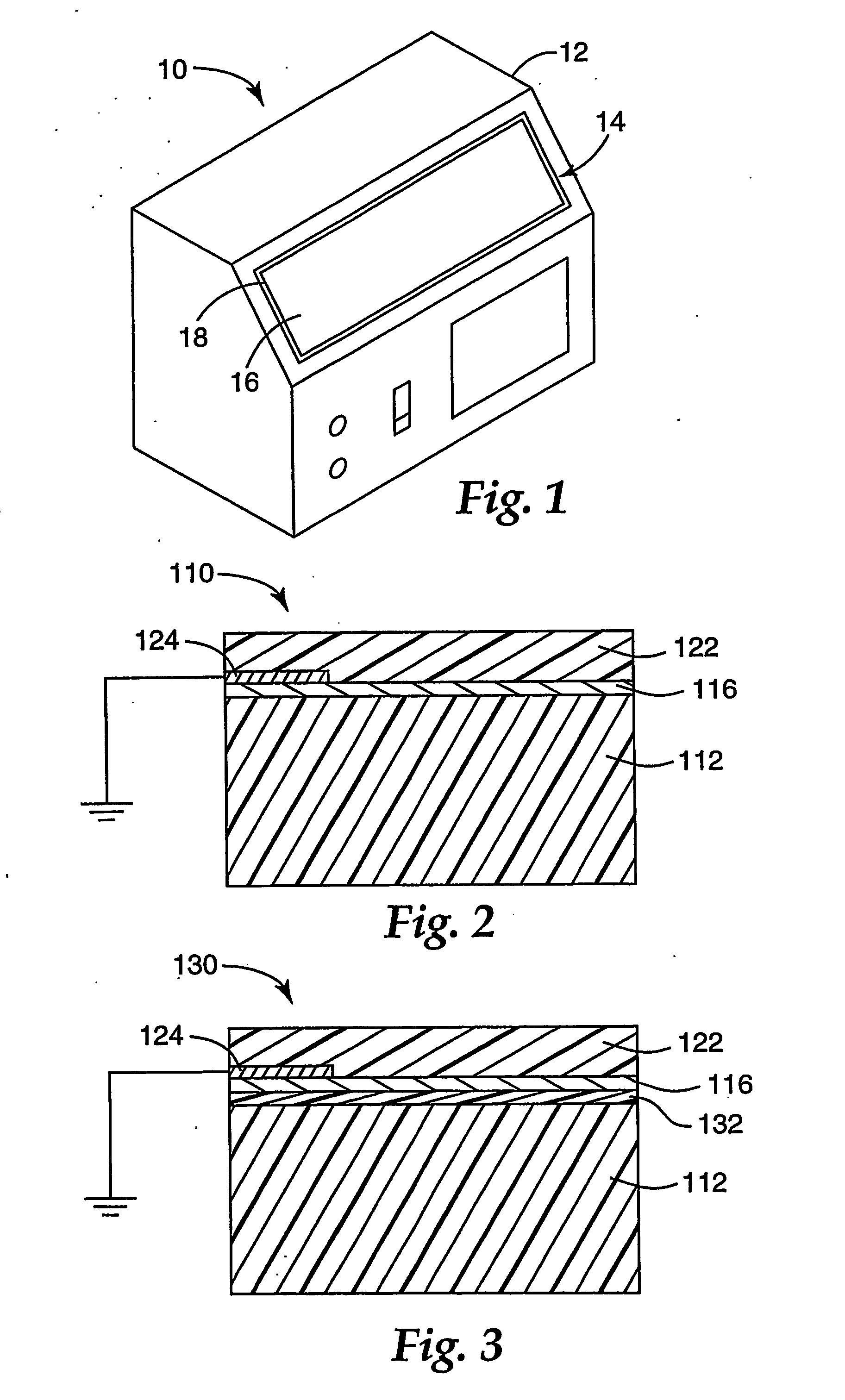
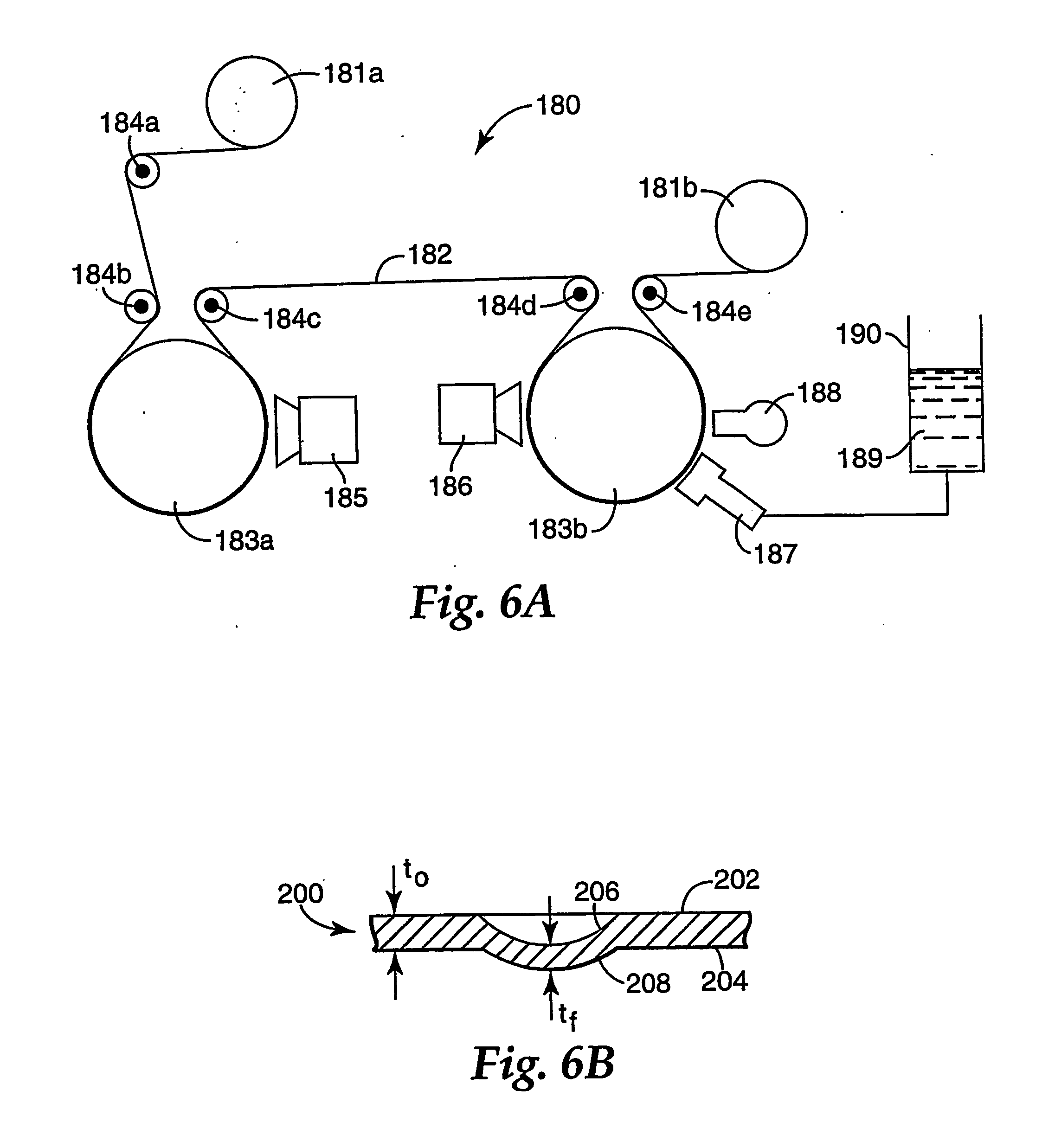
[0075] (Layer 1) An approximately 300 meter long roll of 0.05 mm thick by 508 mm wide PET support (MELINEX™ No. 453 film, DuPont Teijin Films) was loaded into a roll to roll vacuum chamber like that shown in FIG. 6A. The pressure in the vacuum chamber was reduced to 3×10⁻⁴ torr. The support was sequentially plasma pretreated and acrylate coated during one pass at a web speed of 36.6 m / min. The plasma pretreatment utilized a chrome target and an unbalanced dc magnetron operated at 1500 watts power (429 volts and 3.5 amps) under a nitrogen atmosphere with a nitrogen gas flow of 70 sccm. The acrylate coating employed a 50:50 mixture of IRR214 acrylate (UCB Chemicals) and lauryl acrylate that had been degassed for 1 hour by placing a container of the liquid monomer mixture into a bell jar and reducing pressure to approximately 1 millitorr. The degassed monomer was pumped at a flow rate of 2.35 ml / min through an ultrasonic atomizer into a vaporization chamber maintained at 274° C. Using ...

example 2

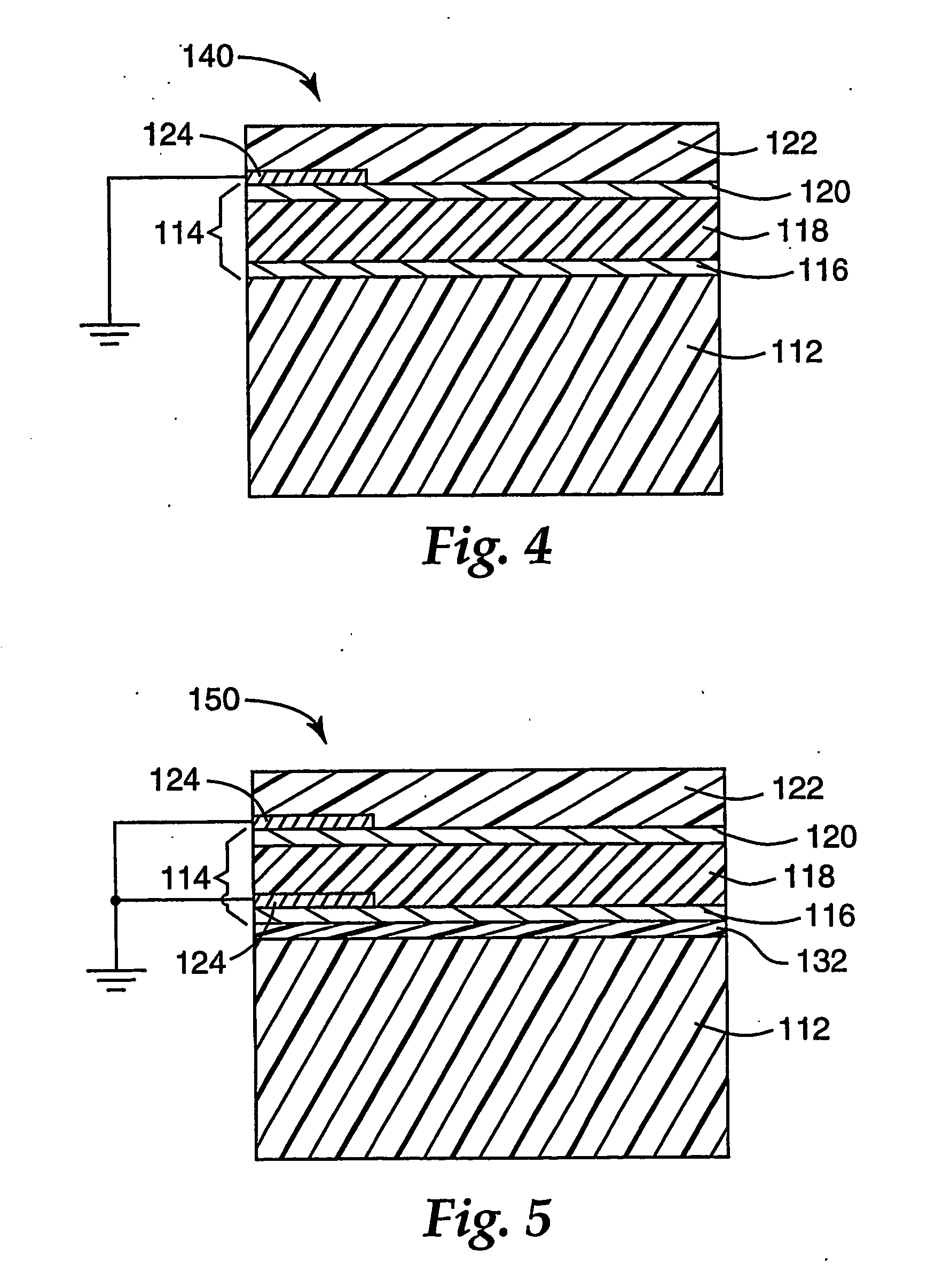
[0081] Using the method of Example 1, a PET support was covered with a five layer acrylate / Ag / acrylate / Ag / acrylate optical stack, but using plasma pretreatment on both the top and bottom of the metal layers. The individual layer differences were as follows:

[0082] (Layer 1) The support plasma pretreatment was as before but at 1000 watts power (402 volts and 2.5 amps) and a nitrogen gas flow of 102 sccm. The monomer flow rate was 2.45 ml / min and the vaporization chamber temperature was 276° C. The monomer vapor was condensed onto the moving web using a −21° C. drum temperature. The electron beam filament was operated at 8.0 kV and 6.5 milliamps.

[0083] (Layer 2) The plasma pretreatment was at 1000 watts power (309 volts and 3.34 amps) and a nitrogen gas flow of 90 sccm. The silver was sputtered at 570 volts and 17.88 amps, a drum temperature of 21° C. and an argon gas flow of 93.2 sccm.

[0084] (Layer 3) The silver surface was plasma pretreated prior to deposition of the spacing layer...

examples 3-5

[0088] Using the method of Example 2, five layer infrared-rejecting acrylate / Ag / acrylate / Ag / acrylate optical stacks with silver layers of varying thickness were formed on a PET support. The resulting films were evaluated for appearance, transmission (Tvis), reflection, solar heat gain coefficient (SHGC), shading coefficient (SC) and sheet resistivity. The processing conditions and evaluation results are set out below in Table 1.

TABLE 1Ex. 3Ex. 4Ex. 5Layer 1Deposited materialMonomersMonomersMonomersLine speed (m / min)36.636.636.6Plasma (Watts)100010001000Drum temp (° C.)−21−21−21Monomer feed (ml / min)2.652.652.65Layer 2Deposited materialAgAgAgLine speed (m / min)35.136.638.1Plasma (Watts)100010001000Drum temp (° C.)262626Sputter power (kW)101010Layer 3Deposited materialMonomersMonomersMonomersLine speed (m / min)36.636.636.6Plasma (Watts)100010001000Drum temp (° C.)−19−19−19Monomer feed (ml / min)2.652.652.65Layer 4Deposited materialAgAgAgLine speed (m / min)35.136.638.1Plasma (Watts)1000100...


PUM

PropertyMeasurementUnit
wavelength regionaaaaaaaaaa
distanceaaaaaaaaaa

Abstract

A device or an enclosed area that can cause or is sensitive to electromagnetic interference (EMI) is shielded by at least partially surrounding the device or the area with a visible light-transmissive film comprising a flexible support, an extensible visible light-transmissive metal or metal alloy layer and a visible light-transmissive crosslinked polymeric protective layer, and optionally connecting at least one grounding electrode to the metal or metal alloy layer. The film has reduced susceptibility to fracture or corrosion compared to commercially available EMI shielding films, especially when bent or deformed.

Description

CROSS REFERENCE TO RELATED APPLICATIONS [0001] This application claims priority to U.S. application Ser. No. 10 / 222,465, “Durable Transparent EMI Shielding Film”, filed Aug. 17, 2002, as a continuation-in-part.FIELD OF THE INVENTION [0002] This invention relates to electrically conductive films suitable for use in electromagnetic interference (EMI) shielding applications. BACKGROUND [0003] EMI shielding films block the transmission of unwanted electromagnetic energy into or out of electronic equipment. A variety of conductive materials can be used for this purpose. For applications in which it is necessary to see through the shielding (e.g., to view a display), windows containing fine wire mesh and specialized transparent films have been used. Transparent EMI shields are also described in U.S. Pat. No. 4,910,090 and 5,489,489 and in European Patent Application No. EP 810452. Commercially available transparent EMI shielding films typically employ a polymer substrate such as PET coate...

Claims


Application Information

Patent Timeline
Patent Type & Authority Applications(United States)
IPC IPC(8): G11B5/64B32B15/08B32B15/082H05K9/00
CPCH05K9/0094Y10T428/12896Y10T428/12396Y10T428/24975Y10T428/26Y10T428/12569Y10T428/265Y10T428/13Y10T428/24967Y10T428/31688Y10T428/31678Y10T428/31692H05K9/00
Inventor FUNKENBUSCH, ARNOLDWBRIGHT, CLARKIFLEMING, ROBERTJ
Owner 3M INNOVATIVE PROPERTIES CO
Why Eureka
Try Eureka