Method of suppressing interferences in systems for detecting objects

a technology of object detection and interference, applied in the field of object detection interference suppression, can solve the problems of further signal processing (spectral analysis, .g. through fft or power), insufficient suppression of trappings and interferences to an adequate extent, etc., and achieves the effect of eliminating transient interference, improving filter effect, and easy implementation

Inactive Publication Date: 2006-02-16
A D C AUTOMOTIVE DISTANCE CONT
View PDF30 Cites 78 Cited by
  • Summary
  • Abstract
  • Description
  • Claims
  • Application Information

AI Technical Summary

Benefits of technology

[0012] For solving this problem, the invention further provides particularly a non-linear digital filtering of the digitized signal (if necessary, after an adequate digital pre-processing, such as e.g. a value squaring for a power analysis), which specifically eliminates the transient interferences. Only in combination and cooperation with this non-linear digital filtering does the special advantage of the pseudo-noise encoding become especially effective, as the interference power is not merely stochastically distributed, but also this portion or component is effectively reduced due to the now transient interferences.
[0013] Preferably, a median filtering is used, in which the median is determined from a respective odd number of consecutive sampled values of a reflection signal detected within a distance gate. Median filtering proves to be efficient and effective and, moreover, can be easily implemented. The median of an odd number K of values is the middle value among the several values, i.e. the (K+1) / 2−smallest value or, what is identical, the (K+1) / 2−largest value, which in general is different from the mean or average value. For instance, for the five values 5, 3, 2, 79 and 1, the median is the value 3, while the mean or average is 18.
[0014] Preferably, a median filter is used which is short in relation to the maximum useful frequency, to be able to reconstruct the superimposed sinusoidal oscillation from the sampled values without significant damping. Preferably, median filters of a length between 3 to 9 values are used. With such short median filters it has been proven to be particularly advantageous when a multi-step or multi-stage median filter is used, in which determination of the median is repeated, i.e. is effected at least two times after another, ensuring in this way a better filter effect with simultaneous low damping. Preferably, a sliding median filter with overlapping windows of the input values is used, i.e. in case of a predetermined length of the filter, only a smaller number (compared to the length of the filter), of examined old input values is replaced by new input values. In particular, a sliding median filter with the step range 1 (i.e. without decimation of the sampling rate) can also be used. In this case, compared to the previous median determination, only the oldest input value respectively is replaced by the current new input value for carrying out the new median determination. This fully maintains the resolution. A two-step or two-stage median filter with a length of 5 values in each stage and a step range of 1 proves to be already extremely effective for the considered applications. Preferably, an oversampling is performed within each distance gate.

Problems solved by technology

This measure alone, however, is not sufficient to suppress trappings and interferences to an adequate extent.
But in the case of high degrees of interference, this could already suffice to make the results of the further signal processing (spectral analysis for Doppler determination e.g. by means of FFT or power analysis e.g. by power integration) useless.

Method used


Image

  • Method of suppressing interferences in systems for detecting objects
  • Method of suppressing interferences in systems for detecting objects
  • Method of suppressing interferences in systems for detecting objects

Examples


Embodiment Construction

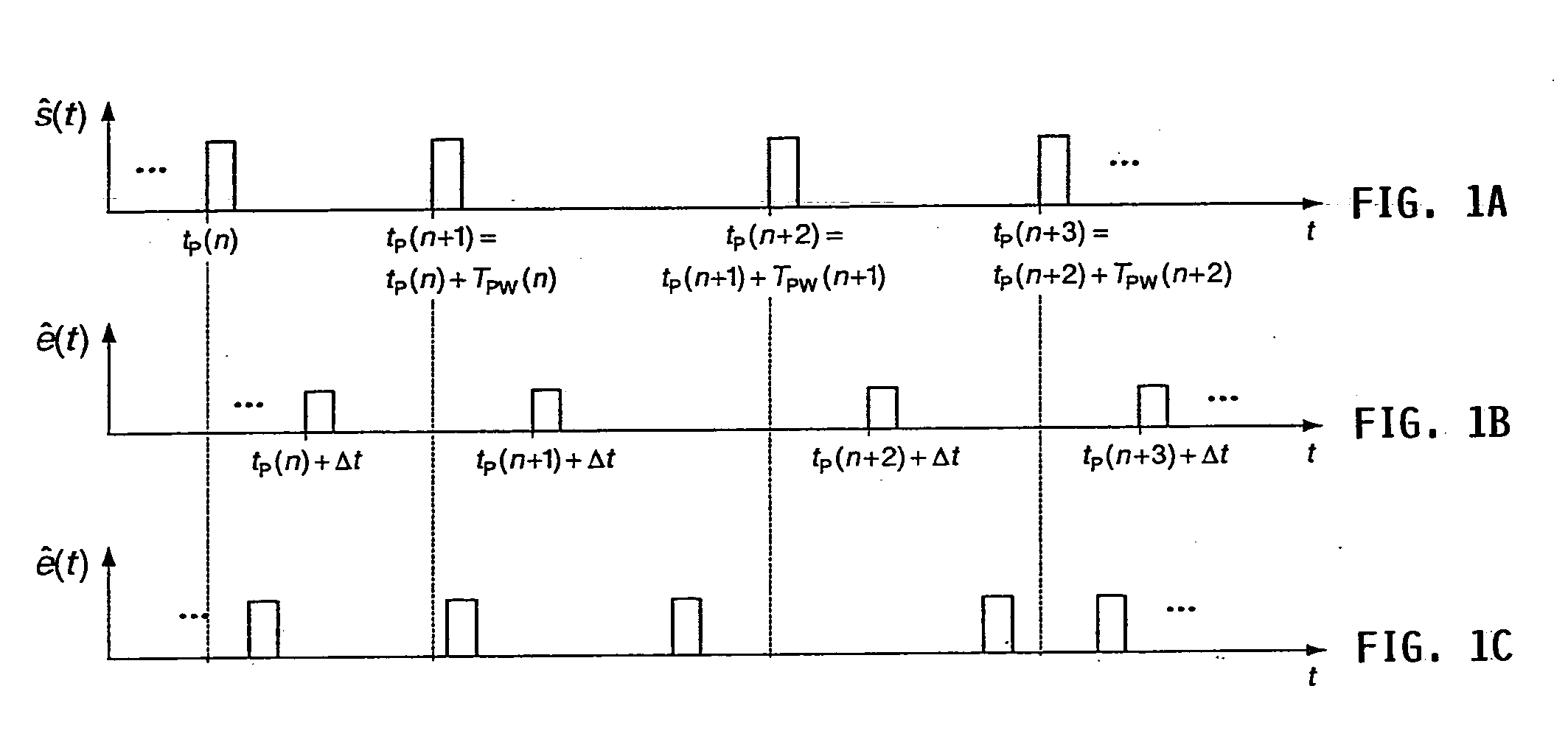
[0035] In FIG. 1A for a pulsed system, the amplitude or envelope ŝ(t) of the transmitted wave of the frequency fs is shown for the case of rectangular pulses. The moments at which the transmit pulses begin are designated herein with tP(n). The distance, i.e. the time spacing, between two consecutive pulses is called the pulse repeat time TPW(n).

[0036] If this wave with the propagation velocity c is reflected on an object at the distance a, after the running or transit time Δt=2a / c the system receives the reflected and in general damped wave e(t). In FIG. 1B the amplitude or envelope ê(t) of the received wave is shown. Thus one can conclude or ascertain the distance of the object from the running time Δt, as long as the running time Δt is always smaller than the pulse repeat time TPW(n); otherwise ambiguity problems do arise—they are referred to as trappings. If the object detected by the wave moves with the relative velocity v relative to the measuring system, then the reflected wa...


PUM


Abstract

In a method for suppressing interferences while detecting objects in a target area, a transmitter transmits a sequence of pulses into the target area, and a receiver detects the resulting reflection signal of the pulses reflected from the objects, within successive time windows that are referenced to the moment of transmitting an individual pulse and thus represent distance gates. The time spacing between the successive individual pulses is variable and randomized according to the pseudo-noise principle within predetermined limits, and the time windows are adapted accordingly. The received reflection signal may be sampled, digitized, digitally pre-processed and digitally filtered in the individual distance gates. A non-linear digital filter, preferably a sliding median filter, is used for the filtering to suppress transient disturbances. The median is determined from an odd number of consecutive sampled values of a reflection signal detected within a distance gate.

Description

CROSS-REFERENCE TO RELATED APPLICATION [0001] This application is a Continuation under 35 U.S.C. §111, 120 and §365 of PCT International Application PCT / DE03 / 02046, filed on Jun. 18, 2003, which designated the United States, and which was published in a language other than English. The entire disclosure of that PCT International Application is incorporated herein by reference.PRIORITY CLAIM [0002] This application claims the foreign priority under 35 U.S.C. §119 of German Patent Application 102 50 607.8, filed on Jun. 18, 2002. The entire disclosure of that German Patent Application is incorporated herein by reference. FIELD OF THE INVENTION [0003] The invention relates to a method for suppressing interferences in systems to detect objects in a target area, in which a sequence of pulses is transmitted by at least one transmitter into the target area and the reflection signals of the pulses are detected by at least one receiver within several time windows representing respective dist...

Claims


Application Information

Patent Timeline
Patent Type & Authority Applications(United States)
IPC IPC(8): G01S13/00G01S7/292G01S7/36G01S13/02G01S13/22G01S13/28G01S13/524G01S13/93H03H17/02
CPCG01S7/023G01S7/2927G01S7/36G01S13/222H03H17/0263G01S13/931G01S2013/9364G01S2013/9367G01S13/5244
Inventor WINTERMANTEL, MARKUS
Owner A D C AUTOMOTIVE DISTANCE CONT
Why Eureka
Try Eureka