Scanning near field ultrasound holography

a near field ultrasound and holography technology, applied in the direction of mechanical measurement arrangement, mechanical roughness/irregularity measurement, instruments, etc., can solve the problems of ultrasonic microscopy, high resolution, and acoustic microscop

Inactive Publication Date: 2006-02-23
NORTHWESTERN UNIV
View PDF10 Cites 41 Cited by
  • Summary
  • Abstract
  • Description
  • Claims
  • Application Information

AI Technical Summary

Benefits of technology

[0007] The present invention relates to a high spatial resolution phase-sensitive technique, which employs a scanning near field ultrasonic holography methodology for imaging buried or other subsurface structures or variation in the specimen. Scanning near field ultrasound holography (SNF...

Problems solved by technology

Further, the acoustic microscope has two other major roadblocks in getting high resolution: (1) impedance mismatches and coupling fluid attenuation that is proportional to f2.
The drawback of ultrasonic microscopy is that it measures only the amplitude due to ultrasonically induced cantilever vibrations.
Moreover, where the sample is particularly thick and has a very irregular surface or high ultrasonic attenuation, only low surface vibration amplitude may be generated.
In such circumsta...

Method used


Image

  • Scanning near field ultrasound holography
  • Scanning near field ultrasound holography
  • Scanning near field ultrasound holography

Examples


Embodiment Construction

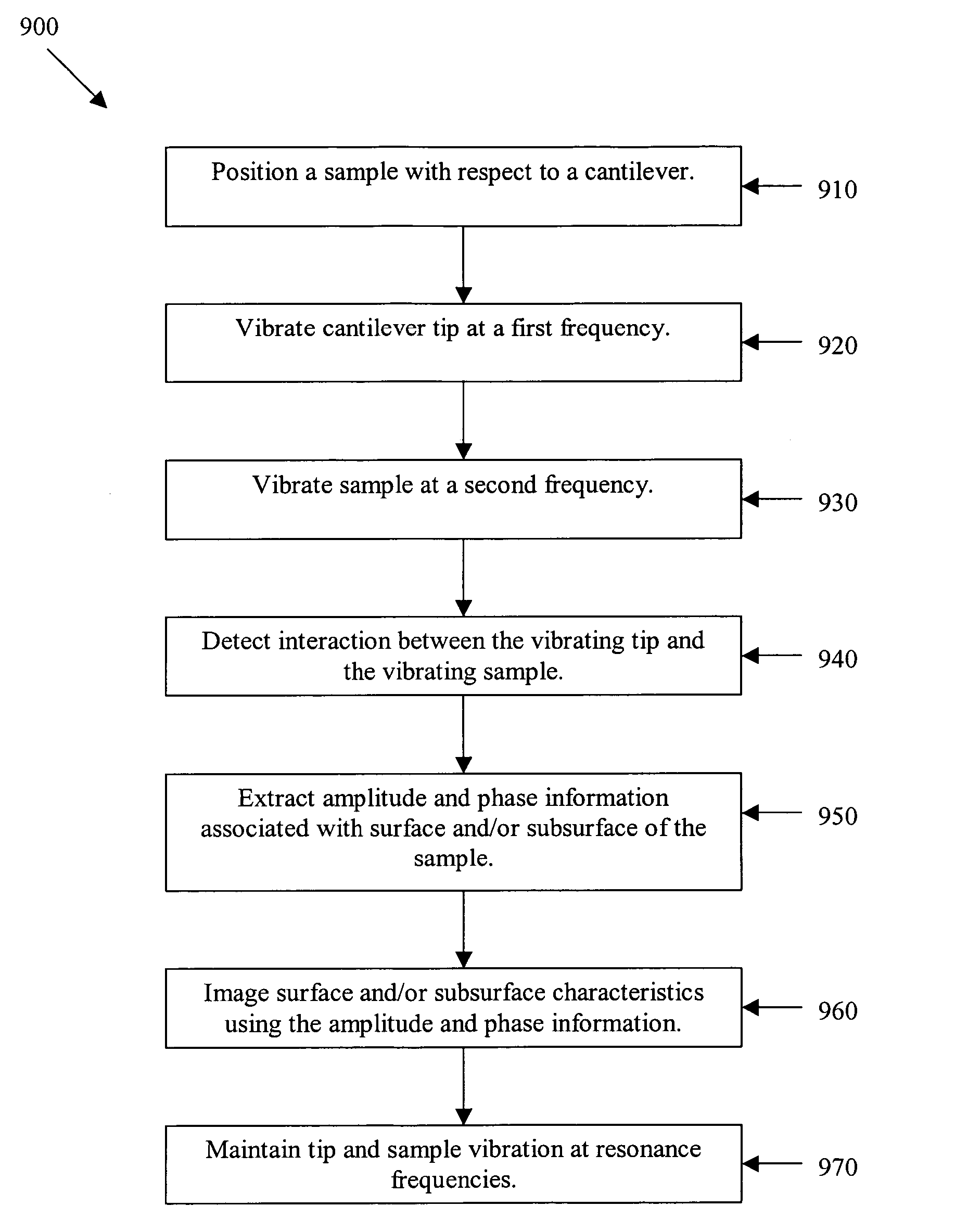
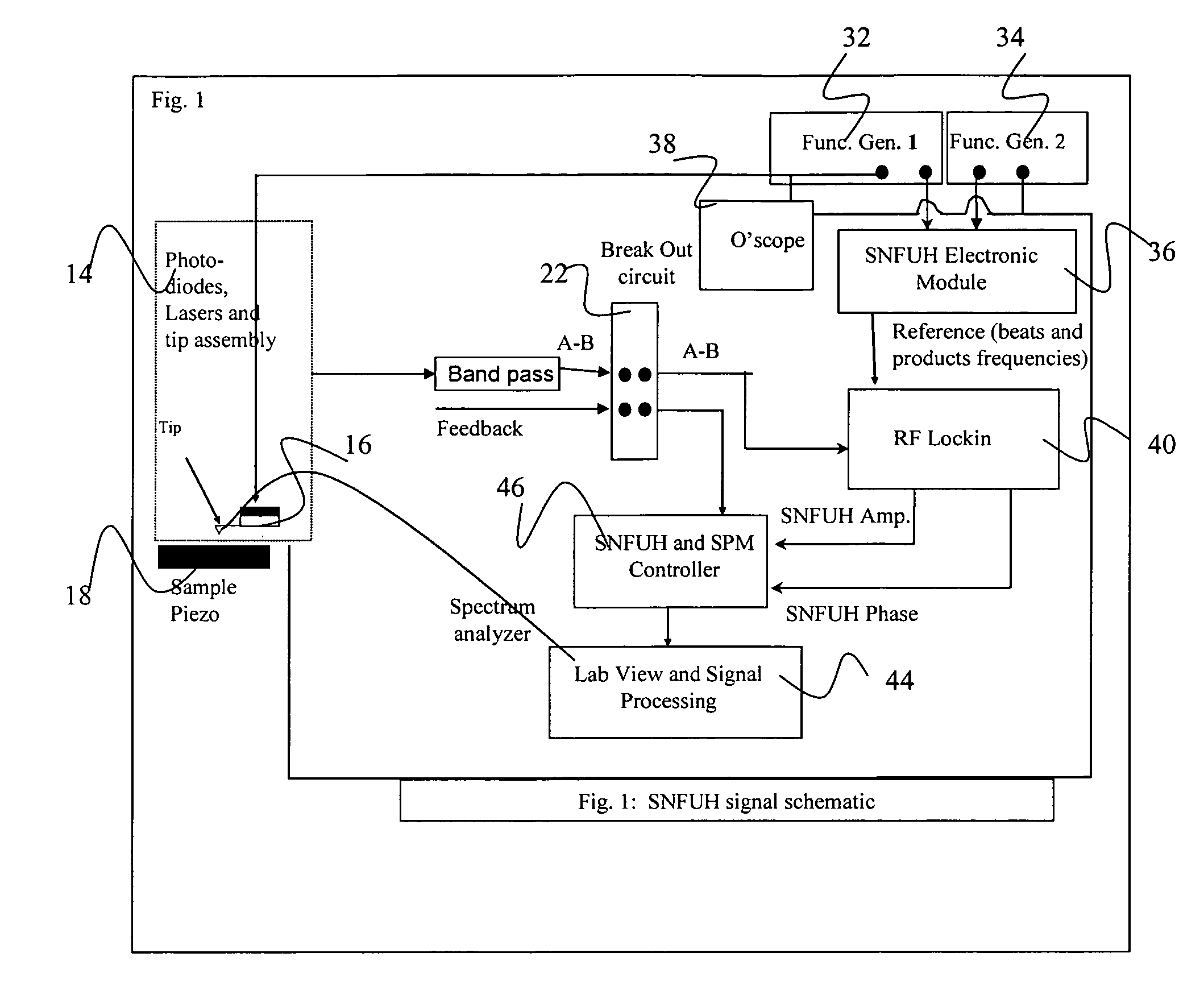
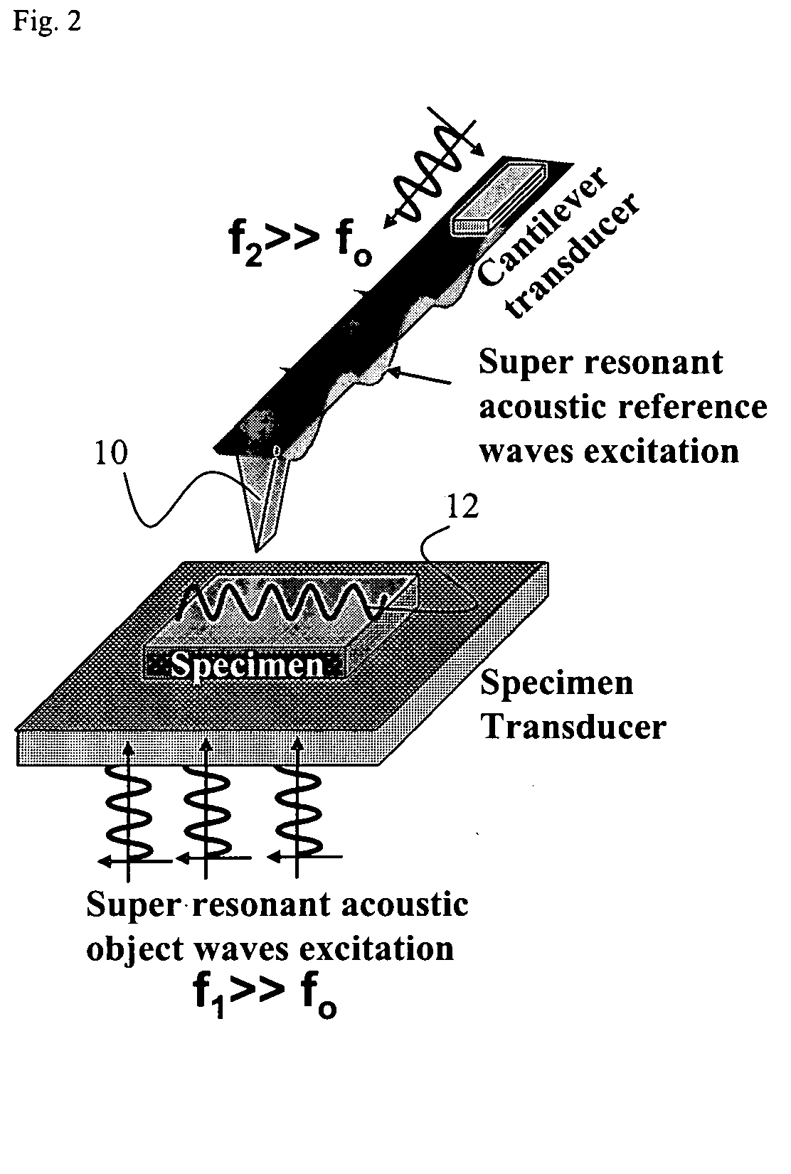
[0032] Certain embodiments of the present invention are directed to a nondestructive, high resolution, sub-surface nanomechanical imaging system. The system is capable of directly and quantitatively imaging the elastic (static) and viscoelastic (dynamic) response of a variety of nanoscale materials and device structures with spatial resolution of a few nanometers depending on the ultrasonic frequencies. For viscoelastic high resolution sub-surface nanomechanical imaging the target maximum probe frequency is around 5-10 GHz, for example. In an embodiment, the maximum relative phase resolution at this frequency is estimated to be 0.001° leading to a viscoelastic time resolution of less than <1 ps. The instrument of certain embodiments of the present invention operates in a manner similar to commercially available scanning probe microscopes (SPMs) in that quantitative, digital, rastered, nanometer-scale images are obtained of the sample elastic modulus, and sample viscoelastic response...


PUM


Abstract

A high spatial resolution phase-sensitive technique employs a scanning near field ultrasound holography (SNFUH) methodology for imaging elastic as well as viscoelastic variations across a sample surface. SNFUH uses a near-field approach to measure time-resolved variations in ultrasonic oscillations at a sample surface. As such, it overcomes the spatial resolution limitations of conventional phase-resolved acoustic microscopy (i.e. holography) by eliminating the need for far-field acoustic lenses.

Description

CROSS-REFERENCE TO RELATED APPLICATIONS [0001] This application is a continuation-in-part of non-provisional application Ser. No. 10 / 913,086 filed Aug. 6, 2004, which claims priority to provisional application Ser. No. 60 / 494,532 filed Aug. 12, 2003, which are hereby incorporated herein by reference in their entirety.STATEMENT REGARDING FEDERALLY SPONSORED RESEARCH OR DEVELOPMENT [0002] N / A BACKGROUND OF THE INVENTION [0003] Known acoustic microscopes are used for imaging structures such as integrated circuit (IC) structures. The spatial resolution, w, of an acoustic microscope is given by: w=0.51⁢ ⁢ϑf.NA where Θ is the speed of sound in the coupling medium, f is the frequency of the acoustic / ultrasonic wave, and N.A. is the numerical aperture of the lens. For a frequency of 1 GHz, the nominal spatial resolution attainable is approximately 1.5 μm. Further, the acoustic microscope has two other major roadblocks in getting high resolution: (1) impedance mismatches and coupling fluid ...

Claims


Application Information

Patent Timeline
IPC IPC(8): G01N29/04G01N13/16G01N29/06G01N29/265G01Q60/24G03H3/00
CPCG01N29/0663G01N29/0681G01N29/069G03H3/00G01N2291/0232G01N2291/02827G01N2291/0427G01N29/265G01Q60/32
Inventor SHEKHAWAT, GAJENDRADRAVID, VINAYAK P.
Owner NORTHWESTERN UNIV
Why Eureka
Try Eureka