Cylinder cutoff control apparatus of internal combustion engine

a control apparatus and internal combustion engine technology, applied in the direction of electric control, machines/engines, output power, etc., can solve the problems of increasing fuel consumption rate, deteriorating fuel economy, and inability to convert or use combustion work as effective work, so as to reduce reduce the tendency for the engine braking effect to be greatly reduced, and effectively suppress any unnatural feeling

Inactive Publication Date: 2006-02-23
HITACHI LTD
View PDF2 Cites 133 Cited by
  • Summary
  • Abstract
  • Description
  • Claims
  • Application Information

AI Technical Summary

Benefits of technology

[0014] As discussed above, in either the intake-valve-advance cylinder cutoff mode (the P-V characteristic diagram (a) in FIG. 16C) or the exhaust-valve-advance cylinder cutoff mode (the P-V characteristic diagram (b) in FIG. 16C) there is a less minus indicated work of the engine, thereby resulting in an undesirably reduced engine braking effect. Only a slight engine braking effect corresponding to an internal friction of the engine exists. Therefore, after a transition from the fuel cutoff mode (see FIG. 16B) to the cylinder cutoff mode (see FIG. 16C), there is an increased tendency for the engine braking effect to be greatly reduced. This means a poor engine braking effect, thus causing an unnatural feeling that the driver experiences an undesirably small engine braking torque.
[0015] Accordingly, it is an object of the invention to provide a cylinder cutoff control apparatus of an internal combustion engine capable of effectively suppressing any unnatural feeling that the driver experiences improper engine braking effects such as an uncomfortable engine braking shock or a poor engine braking effect in a transient state from fuel cutoff to cylinder cutoff, and ensuring a better engine braking feel and smooth engine-braking torque reduction even during the fuel-cutoff-to-cylinder-cutoff transition.

Problems solved by technology

As a result, the major part of combustion work is merely used to compensate for the gas exchange loss, and therefore the combustion work cannot be converted into or used as an effective work.
This causes a deterioration in fuel economy, in other words, an increased fuel consumption rate.

Method used


Image

  • Cylinder cutoff control apparatus of internal combustion engine
  • Cylinder cutoff control apparatus of internal combustion engine
  • Cylinder cutoff control apparatus of internal combustion engine

Examples


Embodiment Construction

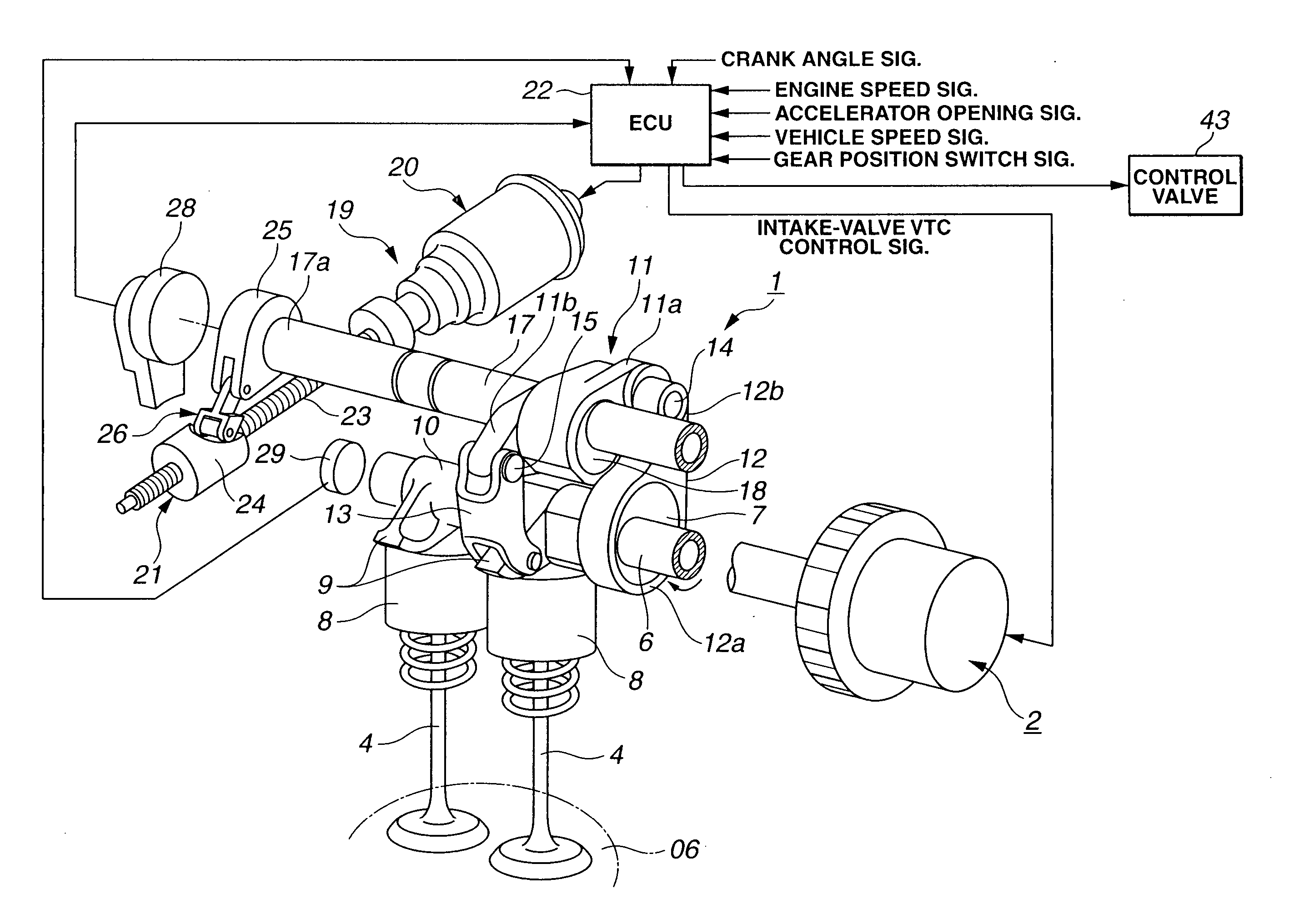
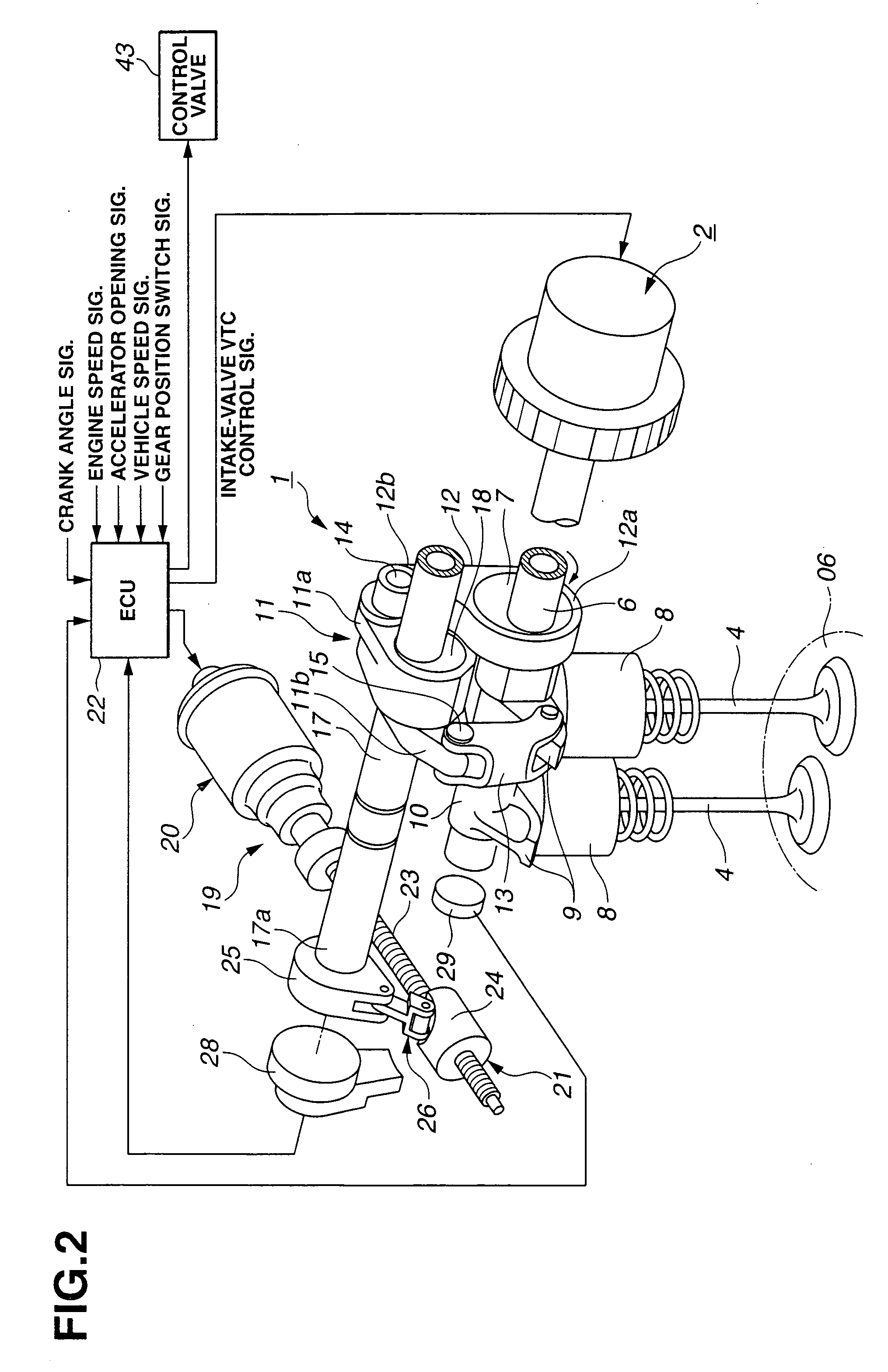
[0042] Referring now to the drawings, particularly to FIGS. 1-3, the cylinder cutoff control apparatus of the embodiment is exemplified in a valve operating device mounted on a six-cylinder internal combustion engine having four valves per cylinder, namely two intake valves 4, 4 (see FIG. 2) and two exhaust valves 5, 5 (see FIG. 3). As described later, the engine cylinder cutoff apparatus of the embodiment is able to stop or cut off, depending on engine / vehicle operating conditions, a first group of engine cylinders, while a second group of engine cylinders are working.

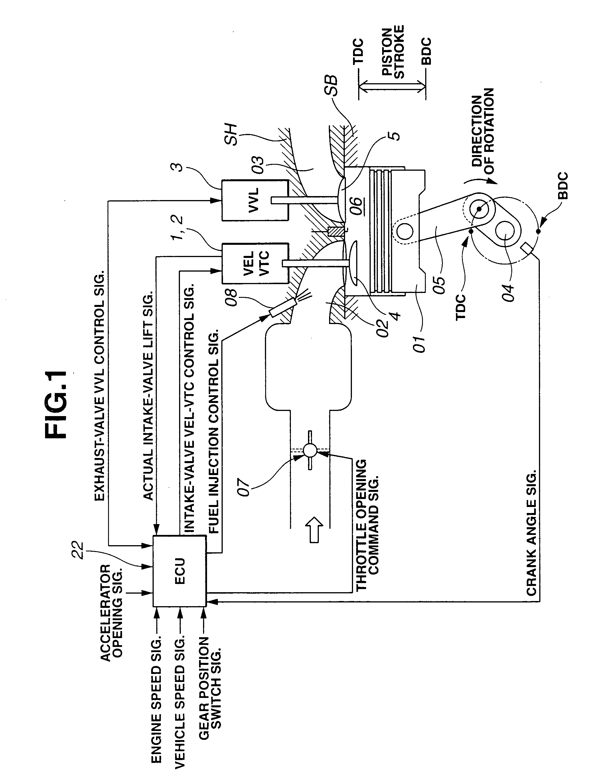
[0043] The construction of the internal combustion engine, to which the cylinder cutoff control apparatus of the embodiment can be applied, is hereunder described in reference to the system diagram of FIG. 1. The engine of FIG. 1 is constructed by a cylinder block SB having a cylinder bore, a reciprocating piston 01 movable or slidable through a stroke in the cylinder bore, a cylinder head SH on the cylinder block SB...


PUM


Abstract

A cylinder cutoff control apparatus of an engine initiates a cylinder cutoff mode only when two conditions, namely a low load condition such as a vehicle cruising condition and an intake valve closure timing controlled to a given timing value before a bottom dead center, are both satisfied. A fuel cutoff mode is executed prior to the cylinder cutoff mode. During a transition to the cylinder cutoff mode, the control apparatus holds an intake valve open timing at a given timing value substantially corresponding to a top dead center, simultaneously with reducing an intake valve lift amount of each intake valve, subjected to cylinder cutoff control, to a zero lift. Immediately when the intake valve lift amount is reduced to below a lift threshold value, an exhaust valve lift amount of each exhaust valve, subjected to the cylinder cutoff control, is controlled to a zero lift.

Description

TECHNICAL FIELD [0001] The present invention relates to an internal-combustion-engine cylinder cutoff control apparatus capable of stopping or cutting off, depending on engine / vehicle operating conditions, a first group of engine cylinders, while a second group of engine cylinders are working, and specifically to the improvement of a technique for electronically controlling mode-switching between (i) a full cylinder operating mode (an all-cylinder operating mode or an all-cylinder active mode) where all of engine cylinders are working and (ii) a partly-inactive cylinder operating mode (a cylinder-in-part operating mode or a cylinder cutoff mode) where the first group of cylinders are inactive and the second group of cylinders are active. BACKGROUND ART [0002] In recent years, there have been proposed and developed various engine cylinder cutoff control technologies. One such engine cylinder cutoff control device has been disclosed in Japanese Patent Provisional Publication No. 10-82...

Claims


Application Information

Patent Timeline
Patent Type & Authority Applications(United States)
IPC IPC(8): F02D17/02F02D13/06F01L1/34
CPCF01L1/185Y02T10/18F01L1/344F01L13/0005F01L13/0026F01L2013/0073F01L2820/032F02D13/0211F02D13/023F02D13/0269F02D13/06F02D41/0002F02D41/0087F02D2041/0012Y02T10/142Y02T10/42F01L1/267Y02T10/12Y02T10/40
Inventor NAKAMURA, MAKOTO
Owner HITACHI LTD
Why Eureka
Try Eureka