
Exhaust system of internal combustion engine

an exhaust system and internal combustion engine technology, applied in the direction of machines/engines, gas passages, gas chambers, etc., can solve the problems of difficult to freely adjust the tone quality within the muffler, and the failure of the driver or the occupant to experience the powerful original sound of the engine or the resultant exhaust sound

Active Publication Date: 2006-02-23
TOYOTA JIDOSHA KK
View PDF3 Cites 21 Cited by
  • Summary
  • Abstract
  • Description
  • Claims
  • Application Information

AI Technical Summary

Benefits of technology

[0009] It is an object of the invention to provide an exhaust system of an internal combustion engine that provides powerful exhaust sound generated by the internal combustion engine, for example, V-type engine, horizontally-opposed type engine and the like while allowing easy adjustment (tuning) of the exhaust sound to a desired tone quality.
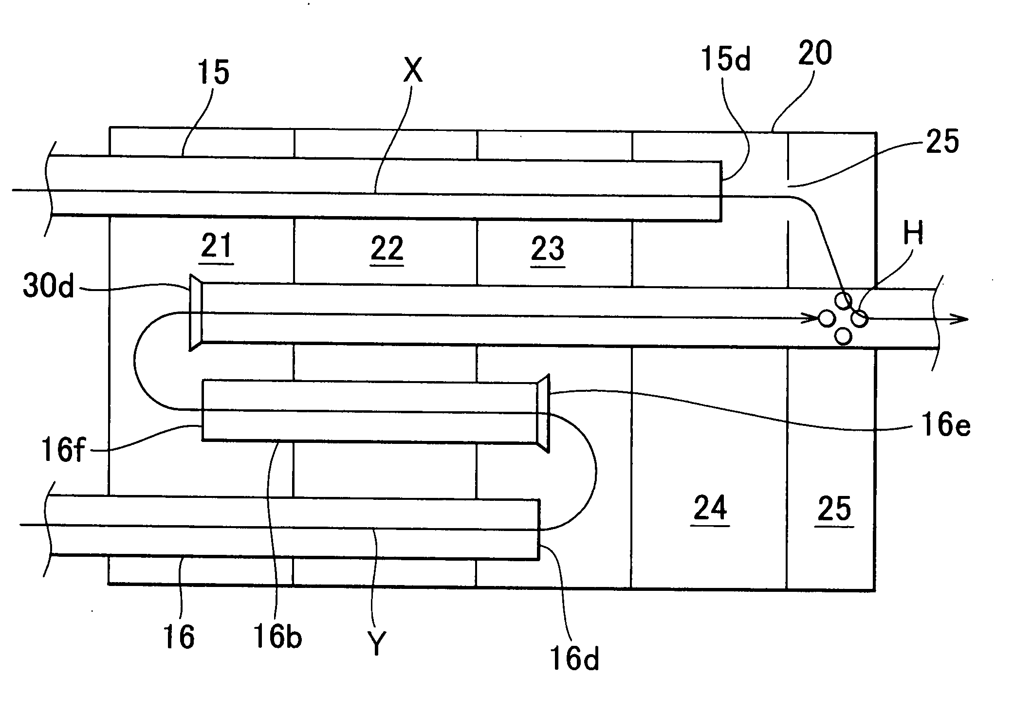
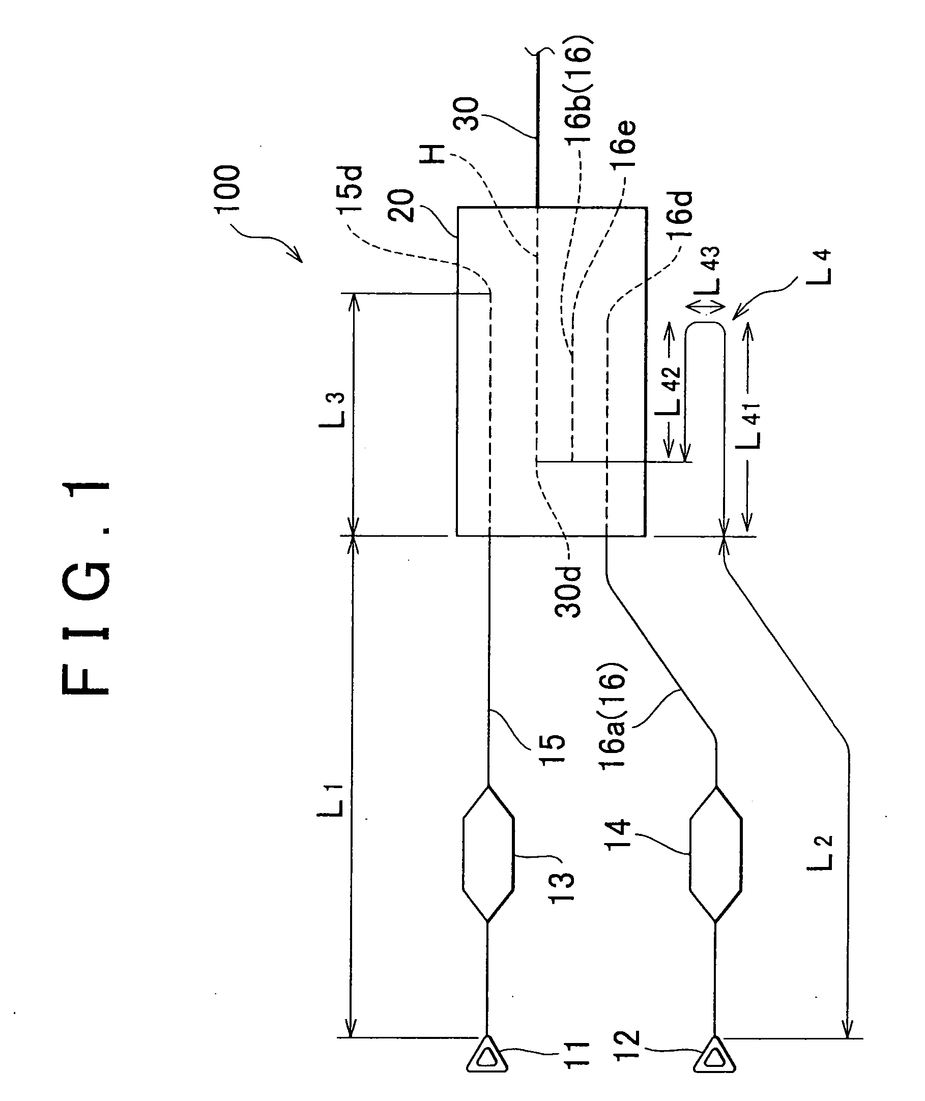
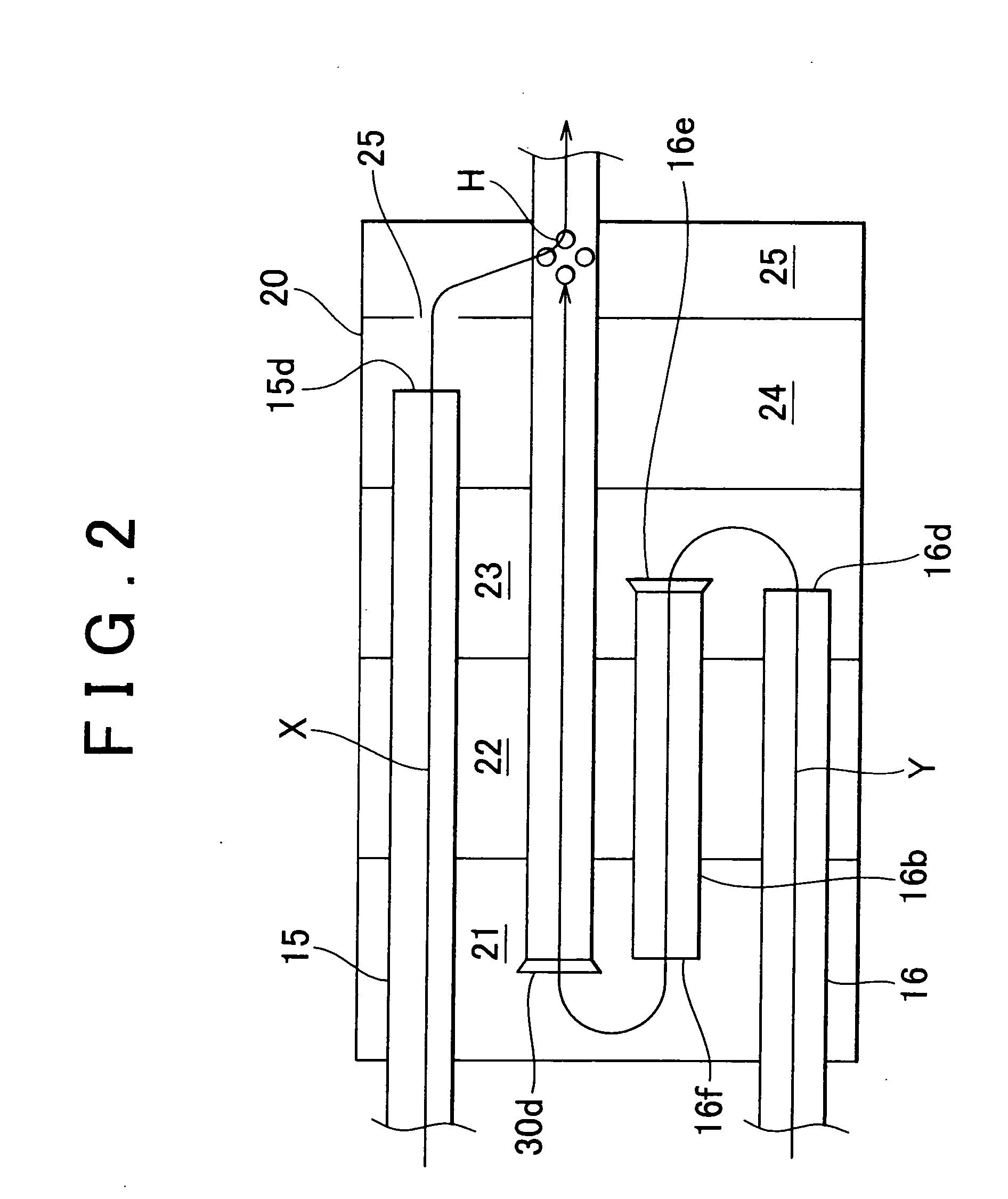
[0011] The exhaust system according to the first aspect of the invention is provided with a dual inlet type muffler, in which the first and the second exhaust pipes serve as an inlet pipe of the single muffler, and the third exhaust pipe serves as an outlet pipe. In the exhaust system, the rear end portion of the first exhaust pipe, that is, an exhaust outlet of the first exhaust pipe locates near the inlet of the third exhaust pipe connected to the exhaust downstream side of the muffler for admitting the exhaust gas. Accordingly the exhaust gas discharged from the first exhaust pipe is substantially directly led to the third exhaust pipe. Accordingly, the exhaust gas that has passed through the first exhaust pipe hardly resides in the muffler nor flows thereinto, the original sound generated by the engine is transmitted to the third exhaust pipe without deteriorating its tone quality. This makes it possible to allow the driver or occupant to experience the dynamic and powerful exhaust sound.
[0012] The length of the first exhaust pipe from the corresponding bank to the muffler is shorter than that of the second exhaust pipe such that the exhaust gas discharged from the first exhaust pipe with the shorter length may be immediately led into the third exhaust pipe, thus restraining the change in quality of the original sound generated by the engine.
[0014] The above-structured exhaust system may allow the length of the path through which the exhaust gas is introduced into the third exhaust pipe via the second exhaust pipe within the muffler to be longer than the length of the path through which the exhaust gas is introduced into the third exhaust pipe via the first exhaust pipe within the muffler. Adjustment of the length of the second exhaust pipe makes it possible to adjust the sound quality with high half order to a required level. The adjustment (tuning) of the exhaust sound transmitted to the third exhaust pipe may be easily performed.

Problems solved by technology

Accordingly the above-structured system fails to allow the driver or the occupant to experience the powerful original sound of the engine or the resultant exhaust sound.
In the above-structured system having the two exhaust pipes each of which has the same length, the sound quality with half order is likely to be erased, and accordingly, it is difficult to freely adjust (tune) the tone quality within the muffler.

Method used


Image

  • Exhaust system of internal combustion engine
  • Exhaust system of internal combustion engine
  • Exhaust system of internal combustion engine

Examples


Embodiment Construction

[0020] An embodiment of the invention will be described referring to the drawings. The identical elements will be designated with the same reference numerals, and the explanation thereof, thus, will be omitted. Unless otherwise specified, the positional relationship in the vertical and horizontal directions will be based on the one shown in the drawings. The dimension ratio of the drawing is not limited to the one shown therein.

[0021]FIG. 1 schematically shows one of preferred embodiment of an exhaust system of the internal combustion engine. An exhaust system 100 is connected to two banks, that is, a right bank and a left bank (not shown) of a V-type engine mounted on the vehicle. Each of those banks is connected to exhaust manifolds 11 and 12, respectively so as to be communicated with a plurality of cylinders provided for the respective banks. Each of the exhaust manifolds 11 and 12 is connected to a front pipe 15 (first exhaust pipe) and a front pipe 16 (second exhaust pipe) in...


PUM


Abstract

In an exhaust system, exhaust manifolds are connected to two banks provided in a V-type engine of a vehicle, respectively, to which front pipes each having a catalytic converter are connected to the exhaust manifolds, respectively. A muffler is provided at an exhaust downstream side of the exhaust pipes, and a rear pipe is further connected to the exhaust downstream side of the muffler. The front pipe has its rear end portion located near a through hole formed in the rear pipe. A path length of one of the front pipes from the bank to the muffler is made shorter than that of the other front pipe.

Description

INCORPORATION BY REFERENCE [0001] The disclosure of Japanese Patent Application No. 2004-240963 filed on Aug. 20, 2004, including the specification, drawings and abstract are incorporated herein by reference in its entirety. BACKGROUND OF THE INVENTION [0002] 1. Field of Invention [0003] The invention relates to an exhaust system of an internal combustion engine. [0004] 2. Description of Related Art [0005] Generally an engine (internal combustion engine) for a vehicle is provided with an exhaust system formed of such components as an exhaust pipe, a catalytic converter and a muffler arranged therein. Especially in the case where the internal combustion engine is of V type, horizontally-opposed type and the like, which has two banks, the exhaust pipe including an exhaust manifold is connected to each of those two banks such that two exhaust pipes are connected to a muffler provided at a downstream side. The structure of the aforementioned exhaust system is disclosed in, for example, ...

Claims


Application Information

Patent Timeline
IPC IPC(8): F01N1/08F01N13/08
CPCF01N2490/06F01N1/084F01N13/011F01N2470/16F01N2470/20F01N1/089
Inventor MABUCHI, TOMOKINOZAWA, YUTAKAASAI, EIJI
Owner TOYOTA JIDOSHA KK
Learn More