Multi-path bar bond connector for an integrated circuit assembly

a technology of integrated circuit assembly and bar bonding, which is applied in the direction of electrical equipment, semiconductor devices, semiconductor/solid-state device details, etc., can solve the problems of wire bonding cost concerns, and achieve the effect of optimizing stress reli

Inactive Publication Date: 2006-02-23
RPX CORP
View PDF11 Cites 18 Cited by
  • Summary
  • Abstract
  • Description
  • Claims
  • Application Information

AI Technical Summary

Benefits of technology

[0003] The present invention is directed to an improved solderable bar bond connector that is particularly well adapted for use with IC chips such as power transistors that require both high current and low current interconnects to a substrate. Additionally, the bar bond connector is configured for optimal stress relief at solder joints connecting it to the chip and the substrate.

Problems solved by technology

However, there are cost concerns associated with wire bonding, and it is more attractive in many cases to form the high current interconnects with soldered bar bond connectors, as described for example in the U.S. Pat. Nos. 5,872,403; 6,083,772; and 6,593,527.

Method used


Image

  • Multi-path bar bond connector for an integrated circuit assembly
  • Multi-path bar bond connector for an integrated circuit assembly
  • Multi-path bar bond connector for an integrated circuit assembly

Examples


Embodiment Construction

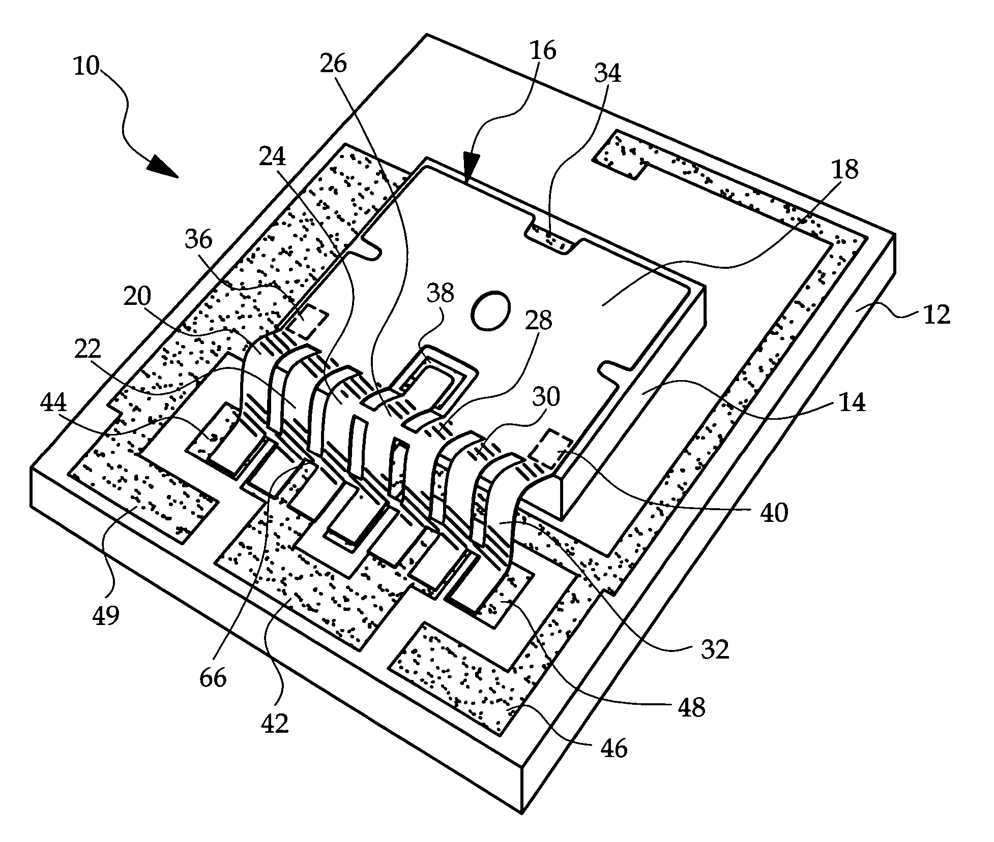
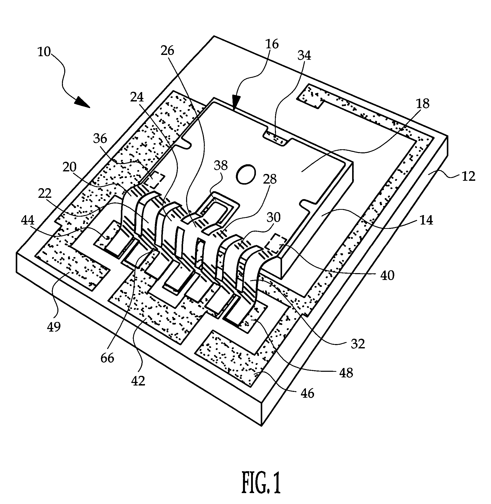
[0010] Referring to the drawings, and particularly toFIG. 1, the reference numeral 10 generally designates an integrated circuit assembly including a circuit board or substrate 12, a bare-die IC chip 14 and a bar bond connector 16 for forming electrical interconnections between bond sites formed on the IC chip 14 and the substrate 12. The bar bond connector 16 includes a plate portion 18 that is placed atop the IC chip 14 and a number of leg elements 20, 22, 24, 26, 28, 30, 32 integral with plate portion 18 and extending from plate portion 18 to multiple bond sites on the substrate 12. In the illustrated embodiment, the substrate 12 is a ceramic substrate, the IC chip 14 is a semiconductor power device such as an IGBT or FET, and the bar bond connector 16 is formed of a highly conductive metal such as copper.

[0011] In most high power applications, the IC chip 14 will have two high current terminals and one or more low current terminals. One of the high current terminals, a FET drai...


PUM


Abstract

A solderable bar bond connector establishes a primary interconnect between a substrate and a high current terminal of an IC chip mounted on the substrate, and one or more secondary interconnects between the substrate and low current terminals of the IC chip. The bar bond connector includes a plate portion soldered to the high current terminal of the IC chip and a plurality of leg elements extending from the plate portion to multiple bond sites on the substrate. The underside of at least one leg element is provided with a secondary circuit including a conductor that is electrically isolated from the respective leg element. The conductor of the secondary circuit is soldered to both the substrate and a low current terminal of the IC chip for establishing a secondary interconnect in addition to the primary interconnect established by the plate portion and the other leg elements.

Description

TECHNICAL FIELD [0001] The present invention is directed to a bar bond connector for electrically coupling integrated circuit terminals to a substrate on which the integrated circuit is mounted, and more particularly to a bar bond connector that provides two or more electrically isolated connections between the integrated circuit and the substrate. BACKGROUND OF THE INVENTION [0002] In many high power electronic applications, it can be cost effective to mount an integrated circuit (IC) chip such as a power transistor directly on a substrate, and to form electrical interconnects between the substrate and conductor pads (also referred to as bond sites) located on the exposed surface of the IC chip. Traditionally, the electrical interconnects have been achieved by wire bonding, with multiple wire bonds per interconnect in cases where high current is required. However, there are cost concerns associated with wire bonding, and it is more attractive in many cases to form the high current ...

Claims


Application Information

Patent Timeline
Patent Type & Authority Applications(United States)
IPC IPC(8): H01L23/48
CPCH01L23/488H01L23/492H01L2924/1305H01L2924/1306H01L2924/14H01L23/49562H01L23/49844H01L24/40H01L2924/01029H01L2924/01033H01L2924/13055H01L2924/00H01L2924/15787H01L2224/40225H01L2224/40091H01L2224/37011H01L2224/84801H01L2224/83801H01L2924/00014H01L2224/37599H01L24/37H01L24/84H01L2224/37099
Inventor OBERLIN, GARY E.OMAN, TODD P.
Owner RPX CORP
Why Eureka
Try Eureka