Supercharge Your Innovation With Domain-Expert AI Agents!

Monopole field electric motor generator

Inactive Publication Date: 2006-02-23
CLEARWATER HLDG +2
View PDF16 Cites 61 Cited by
  • Summary
  • Abstract
  • Description
  • Claims
  • Application Information

AI Technical Summary

Benefits of technology

[0016] A still further objective is to provide such a machine that is useful as a power converter.
[0017] Other features and advantages of the described apparatus and method of use will become apparent from

Problems solved by technology

However, the prior art fails to teach a rotating electromagnetic machine that provides electromagnetic fields immersed in monopole permanent magnet fields of opposite polarities as is shown in the present apparatus.

Method used


Image

  • Monopole field electric motor generator
  • Monopole field electric motor generator
  • Monopole field electric motor generator

Examples


Embodiment Construction

[0033] The above described drawing figures illustrate the described apparatus and its method of use in at least one of its preferred, best mode embodiments, which is further defined in detail in the following description. Those having ordinary skill in the art may be able to make alterations and modifications to what is described herein without departing from its spirit and scope. Therefore, it must be understood that what is illustrated is set forth only for the purposes of example and that it should not be taken as a limitation in the scope of the present apparatus and method of use.

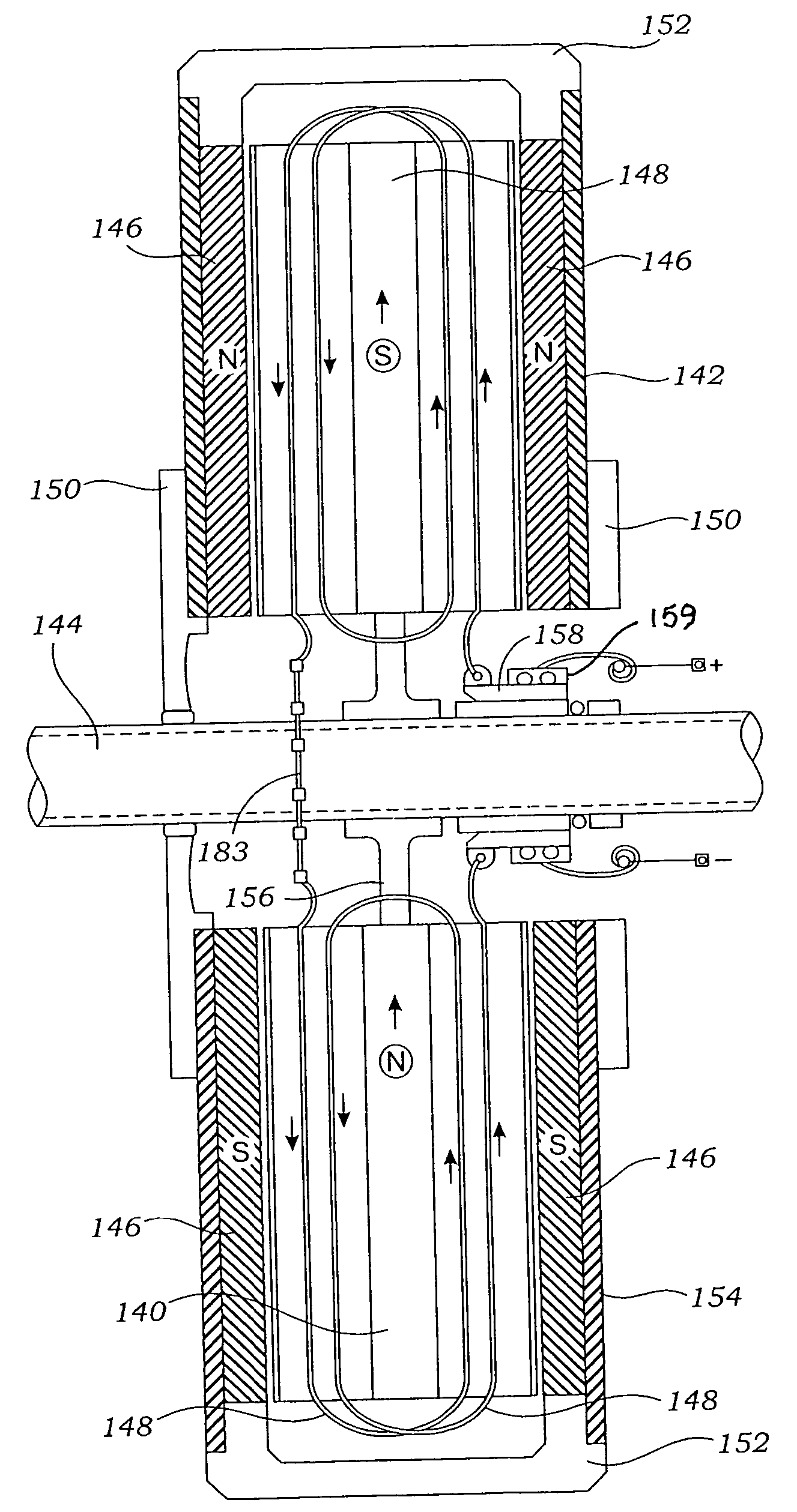
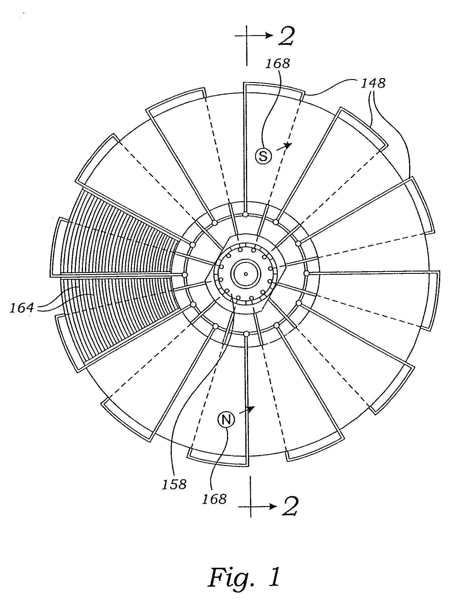
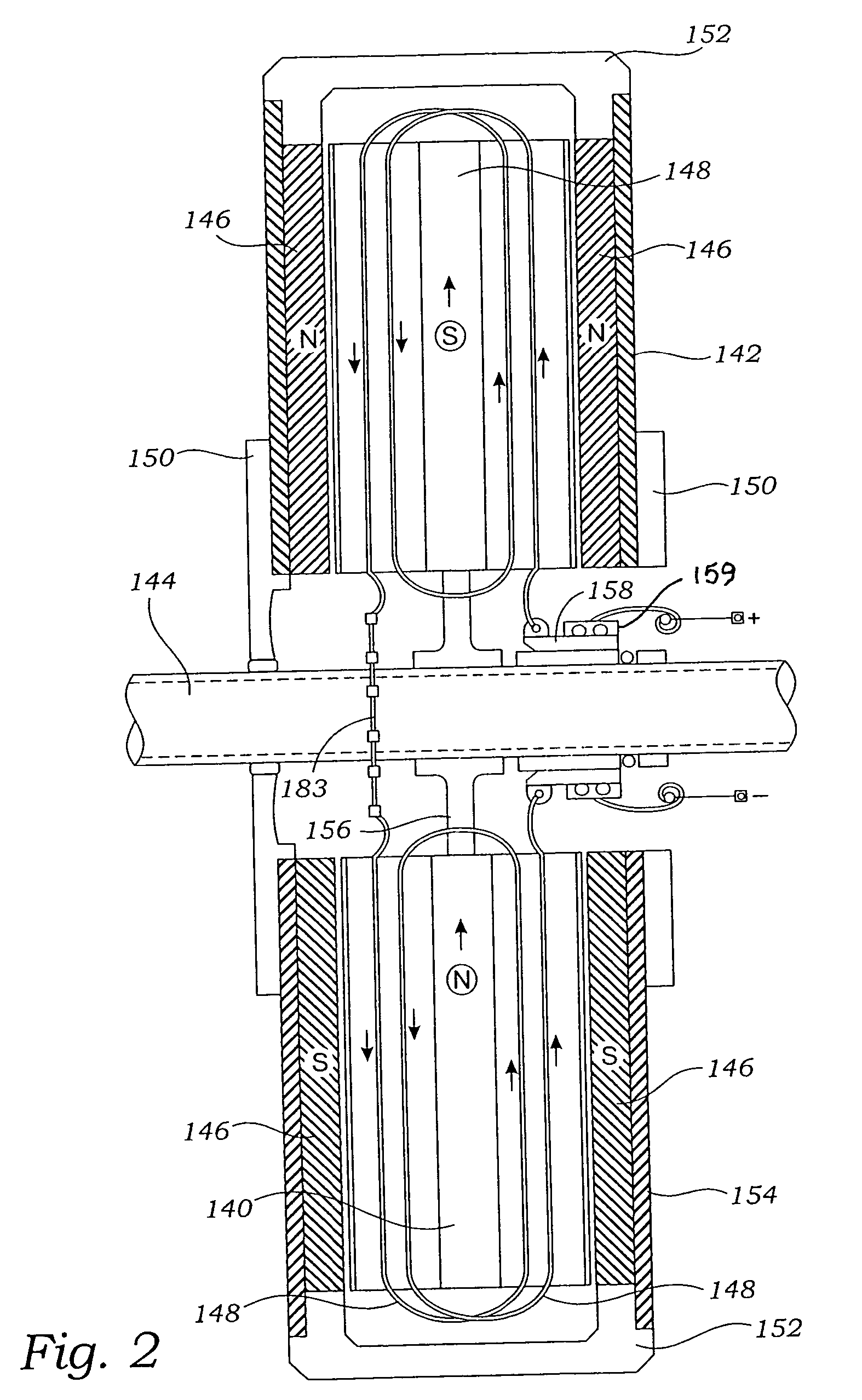
[0034] A rotating electromagnetic apparatus comprises a stator including a stator frame 152 supporting parallel spaced apart, disc-shaped permanent magnet sets, wherein each of the magnet sets comprises plural, spaced apart, co-planar magnet segments 146. The segments 146 are arranged with pairs of opposing N-N and S-S permanent magnet poles, as shown by the letters “S” for south pole and “N” for nort...


PUM


Abstract

A rotating electromagnetic apparatus has a stator including a stator frame supporting parallel spaced apart, disc-shaped permanent magnet sets. Each of the magnet sets is formed as plural, spaced apart, co-planar magnet segments. The segments are arranged with permanent magnet poles of opposite polarity in an alternating sequence. A rotor provides a magnetically permeable rotating rotor frame mounted on an axle and supported by the stator frame. The rotor frame provides a plurality of radially oriented, toroidally wound coils. Like poles of the magnet sets are set in opposing, face-to-face positions with the rotor between them. A current supplying commutator engages the rotor such that each of the coils provides electromagnet poles positioned alternately for attraction and repulsion of the electromagnet poles with respect to the permanent magnet poles thereby causing rotor rotation.

Description

RELATED APPLICATIONS [0001] This application claims international priority from a prior filed U.S. Provisional Patent Application having Ser. No. 60 / 603,444 filed with the United States Patent Office on Aug. 20, 2004 and which is copending with this present non-provisional application. Said Provision Patent Application is hereby incorporated by reference into the present non-provisional application.BACKGROUND [0002] 1. Field of the Present Disclosure [0003] This disclosure relates generally to electric motors and electric generators and more particularly to such rotating electromagnetic machines having monopole fields. [0004] 2. Description of Related Art [0005] The following art defines the present state of the field of the apparatus described and claimed herein: [0006] Tu et al, US 2004 / 0135452, discloses a flat rotary electric generator that includes at least one toroidal coil structure for cutting magnetic lines to induce a current and at least one disc-shaped magnetic pole stru...

Claims


Application Information

Patent Timeline
IPC IPC(8): H02K16/04H02K21/24
CPCH02K23/04H02K23/64H02K23/54H02K21/24
Inventor BOJIUC, DUMITRU
Owner CLEARWATER HLDG
Features
  • R&D
  • Intellectual Property
  • Life Sciences
  • Materials
  • Tech Scout
  • Unparalleled Data Quality
  • Higher Quality Content
  • 60% Fewer Hallucinations
Learn More