

Image signal processing apparatus and phase synchronization method
- Summary
- Abstract
- Description
- Claims
- Application Information
AI Technical Summary
Benefits of technology
Problems solved by technology
Method used
Image

Examples
first embodiment
[0045] An image signal processing apparatus of a first embodiment of the present invention will be explained first by referring to FIG. 7 to FIG. 8.
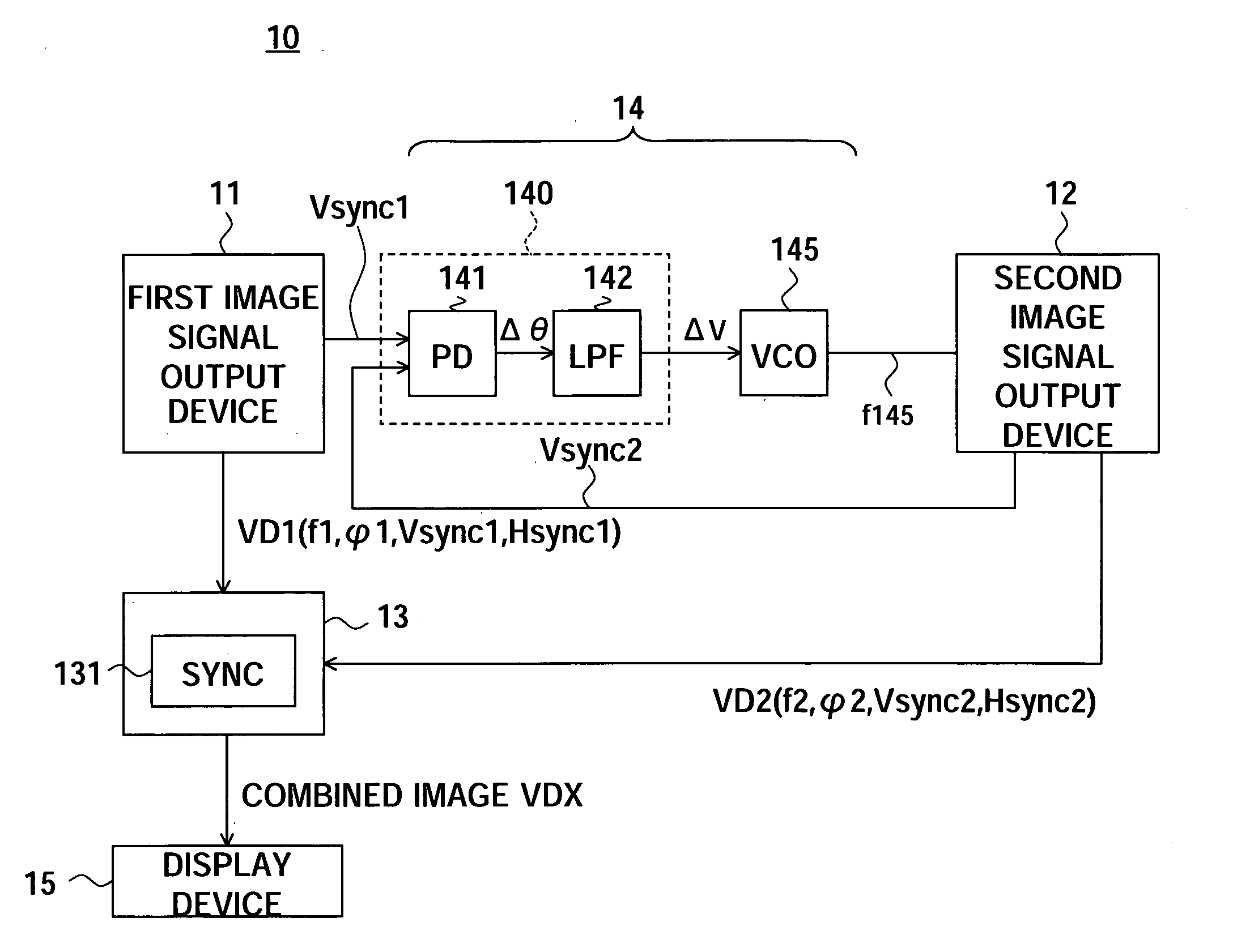
[0046] An image signal processing apparatus 10 of the first embodiment of the present invention illustrated in FIG. 7 has a first image signal output device 11, second image signal output device 12, image signal combining device 13, synchronization signal generation circuit (PLL: Phase-Locked Loop) 14, and display device 15.
[0047] The first image signal output device 11 is for example a television signal receiver, and the first image signal VD1 output from the first image signal output device 11 is for example a television picture signal.
[0048] The second image signal output device 12 includes for example a graphic image generation computer, and the second image signal VD2 output from the second image signal output device 12 is for example a computer graphic image signal after moving picture processing such as GUI (Graphic User's Inte...
second embodiment
[0079] An image signal processing apparatus 10A of a second embodiment of the present invention will be explained next by referring to FIG. 9.
[0080] There are many cases where a first image signal output device 11A and a second image signal output device 12A are located considerably far apart. Under such conditions, the first image signal output device 11A incorporates a tuner 110A outputting a first video signal, a complete integration type phase comparison unit 140A having a phase comparison circuit 141 and an LPF 142, a voltage to( / ) current conversion circuit 143 for converting voltage to current, and a display unit 15 and the second image signal output device 12A incorporates a current to( / ) voltage conversion circuit 144 for converting current to voltage, the VCO 145, and an animation image signal generation unit 145.
[0081] The animation image signal generation unit 145 generates an animation image signal for combination with the TV image signal output from the tuner 110A.
[...
third embodiment
Modification of Third Embodiment
[0096] In an image signal processing apparatus 10B of the third embodiment constituted by a personal computer, the distance between the tuner 110A able to receive the television broadcast and the GUI image signal generation device 120B is short. Accordingly, the distance between the complete integration type phase comparison unit 140 and the VCO 145 and the GUI image signal generation device 120B is short. Accordingly, as explained in the second embodiment, there is only a low possibility of external noise being superimposed between the complete integration type phase comparison unit 140A and the VCO 145 due to a long distance between the tuner 110A able to receive the television broadcast and the GUI image signal generation device 120B. However, as explained above, when all of the circuits illustrated in FIG. 12 are integrally formed, there also exists a possibility of high frequency noise and / or crosstalk from the tuner 110A able to receive the tele...
PUM
 Abstract
Description
Claims
Application Information