
Multi-layered ceramic tube for fuel containment barrier and other applications in nuclear and fossil power plants
- Summary
- Abstract
- Description
- Claims
- Application Information
AI Technical Summary
Benefits of technology
Problems solved by technology
Method used
Image

Examples
example 1
Strength Measurements of Silicon Carbide Ceramic
[0077]FIG. 8 is a summary of temperature versus strength data for various types of silicon carbide composites, similar to the composite layer of the present ceramic tubes, as compared to conventional zirconium alloy. Data is taken from the open literature. The abbreviations used in FIG. 8 are explained in the following table.
AbbreviationMeaningSourceSiC - cgSiC / SiC composite with cg-Nicalon fibersS. J. Zinkle andLL. Snead ofORNLSiC - hi-nicSiC / SiC composite with Hi-Nicalon fibersH. Ichikawawith PIP matrix and BN interphaseof NipponCarbonSiC - Type-sSiC / SiC composite with Hi-Nicalon type-SH. Ichikawafibers with PIP matrix and BN interphaseof NipponCarbonSiC -SiC / SiC composite with Tyranno-SAT. Nozawa andTyrannofibers with CVI matrix and PyC interphaseL. L. Sneadof ORNLZirc-4Framatome low-tin Zircaloy-4M. C. BilloneBilloneof ANLZirc-2Zircaloy-2E. Lahoda
[0078] As illustrated in FIG. 8, zircaloy loses virtually all of its strength at te...
example 2
Fabrication of Ceramic Tubes
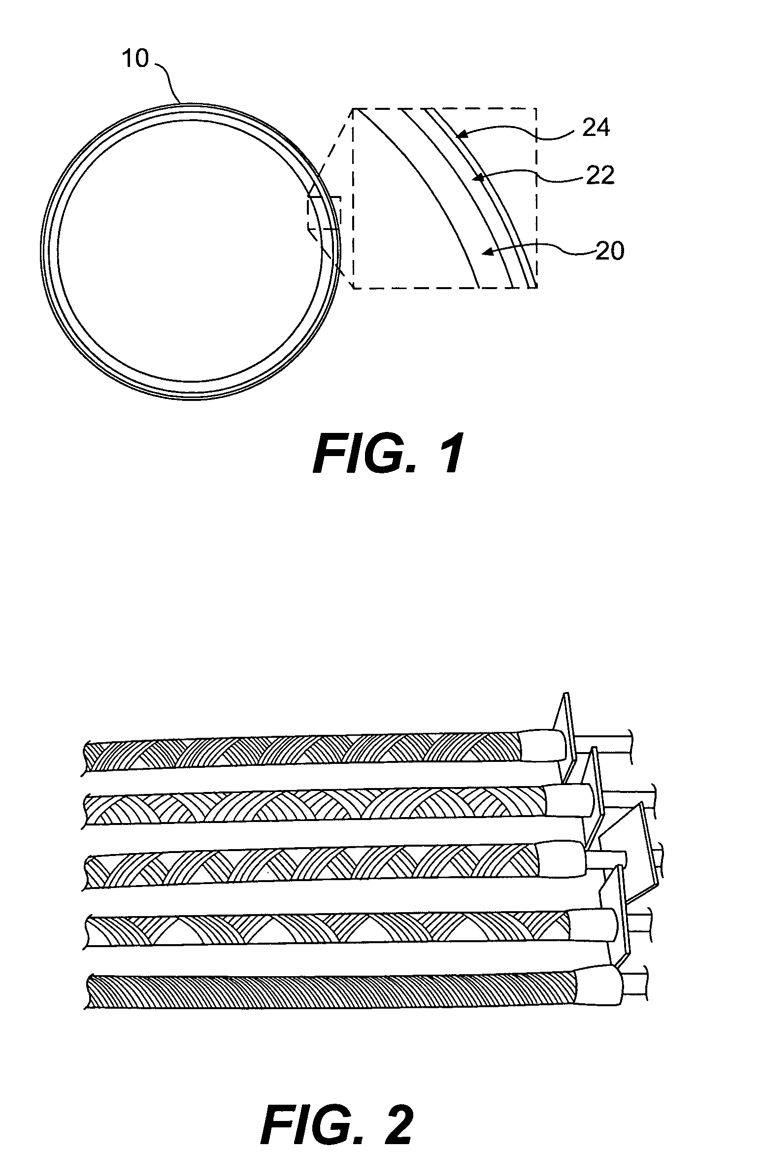
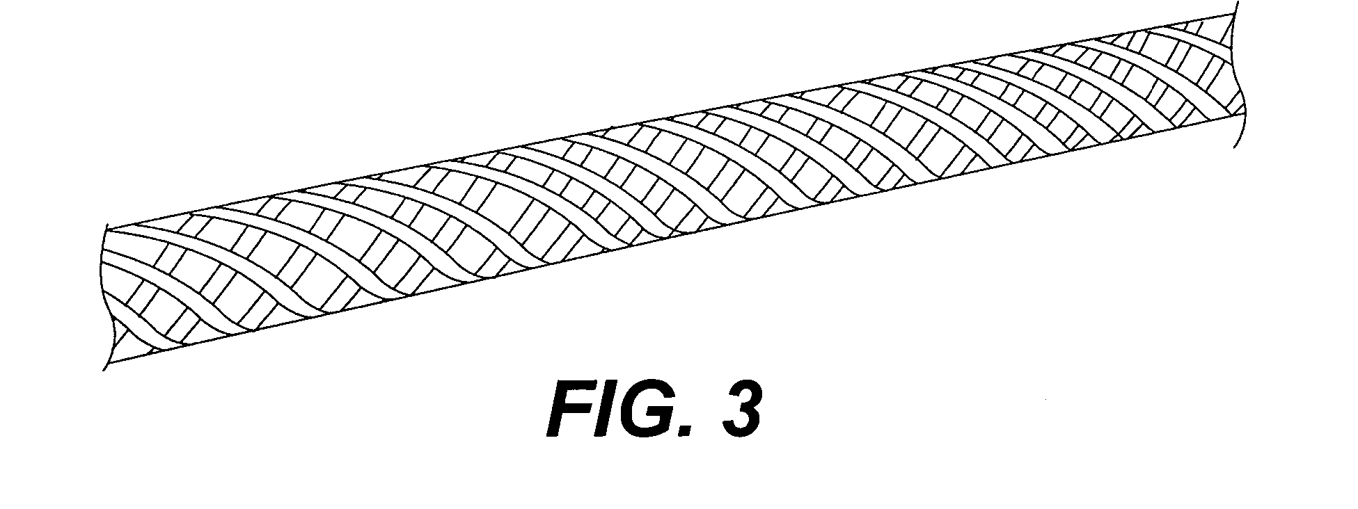
[0079] Exemplary two-layered ceramic tubes of the present invention were formed by the following process. First, Chemical Vapor Deposition (CVD) processes were used to form the inner monolith layer of high purity beta phase stoichiometric silicon carbide, according to techniques known in the art. Second, commercially available fiber tows, formed of 500 to 1600 high purity, beta phase, silicon carbide fibers of 8 to 14 micron diameter, were wound tightly on the inner monolith tube, in a variety of winding patterns and using a variety of winding angles, as shown in FIGS. 2 and 3, to make “pre-forms.”
[0080] These “pre-forms” were then coated with a thin pyrolytic carbon interface layer, and then impregnated with a SiC matrix, using an isothermal pulsed flow technique of chemical vapor infiltration, described as “Type V” in T. M. Besmann et al., “Vapor Phase Fabrication and Properties of Continuous Filament Ceramic Composites,” Science 253:1104-1109 (Sep. 6,...
example 3
Fabrication of Prior Art Tubes
[0082]FIG. 9B illustrates two silicon carbide tubes fabricated according to the method set forth in Feinroth et al. After formation of a relatively thick monolith layer (about 0.125 inches), the tubes were covered with silicon carbide. The left tube was covered with hoop-wound silicon carbide fibers, and the right tube was covered with woven or braided silicon carbide fibers. Further details are provided in H. Feinroth et al., “Progress in Developing an Impermeable, High Temperature Ceramic Composite for Advanced Reactor Clad Application,” American Nuclear Society Proceedings—ICAPP conference (June 2002). The pre-forms were impregnated with a SiC matrix, using the method described in Example 2.
PUM
| Property | Measurement | Unit |
|---|---|---|
| Temperature | aaaaa | aaaaa |
| Temperature | aaaaa | aaaaa |
| Fraction | aaaaa | aaaaa |
Abstract
Description
Claims
Application Information