
Pseudo-random number generation method and pseudo-random number generator

a pseudo-random number and number generation technology, applied in the field of pseudo-random number generation method and pseudo-random number generator, can solve the problems of weak encryption strength (strength of cipher), poor security,

Inactive Publication Date: 2006-02-23
KOBAYASHI AKIRA +1
View PDF6 Cites 43 Cited by
  • Summary
  • Abstract
  • Description
  • Claims
  • Application Information

AI Technical Summary

Benefits of technology

"The present invention provides a method and program for generating pseudo-random numbers using a linear feedback shift register. The invention allows for easy and dynamic changes to the construction of the linear feedback shift register while maintaining high encryption strength and confidentiality of information. The invention also allows for higher throughput with keeping high encryption strength. The technical effects of the invention include improved security and performance of the pseudo-random number generator in software."

Problems solved by technology

Thus, in case the linear feedback shift register 103 whose construction is fixed is used as the pseudo-random number generator 101 as it is, there are problems such as weak encryption strength (strength of cipher) and poor security.

Method used


Image

  • Pseudo-random number generation method and pseudo-random number generator
  • Pseudo-random number generation method and pseudo-random number generator
  • Pseudo-random number generation method and pseudo-random number generator

Examples


first embodiment

[0125] The first embodiment of the present invention is explained by referring to the drawings.

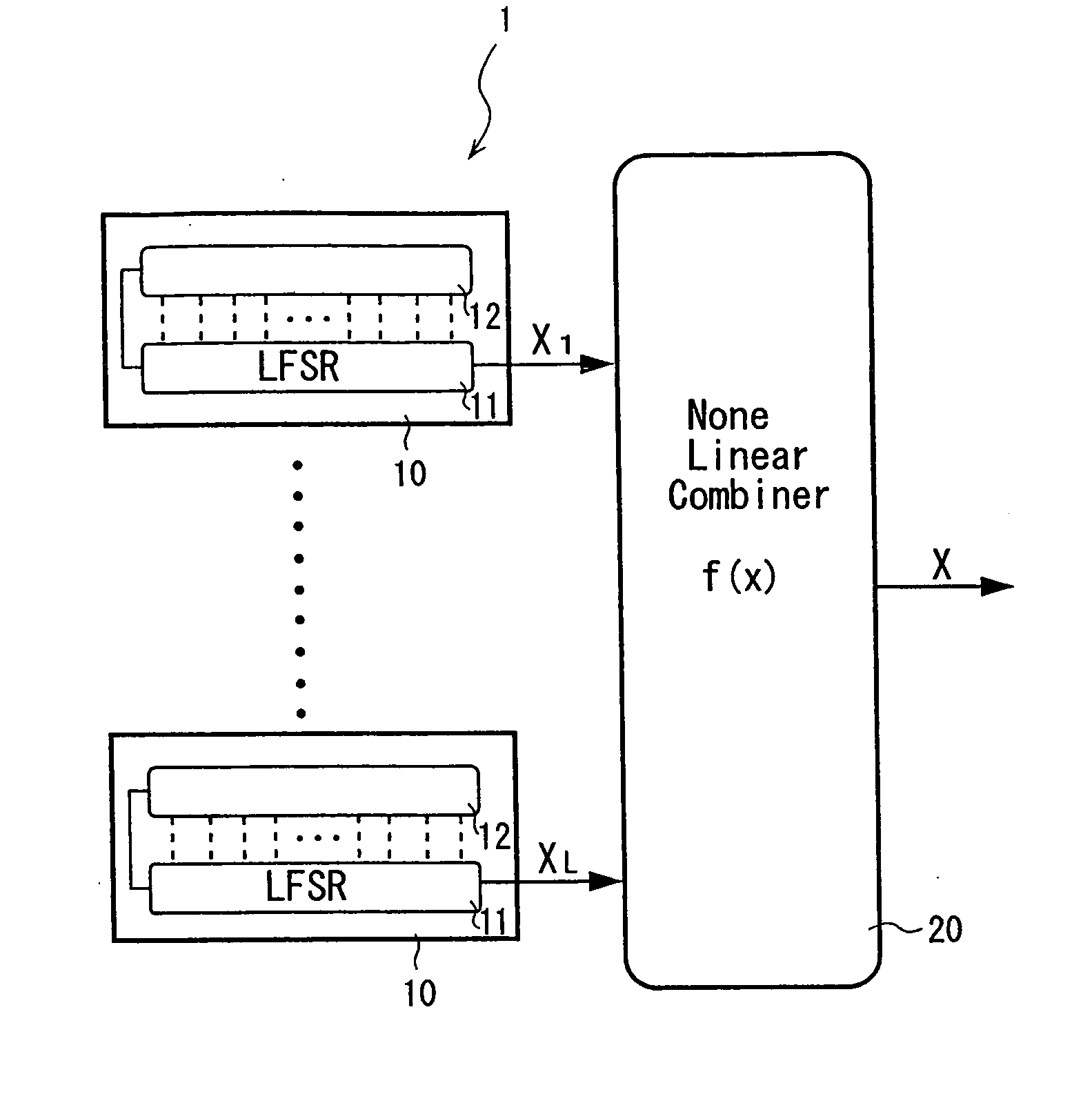
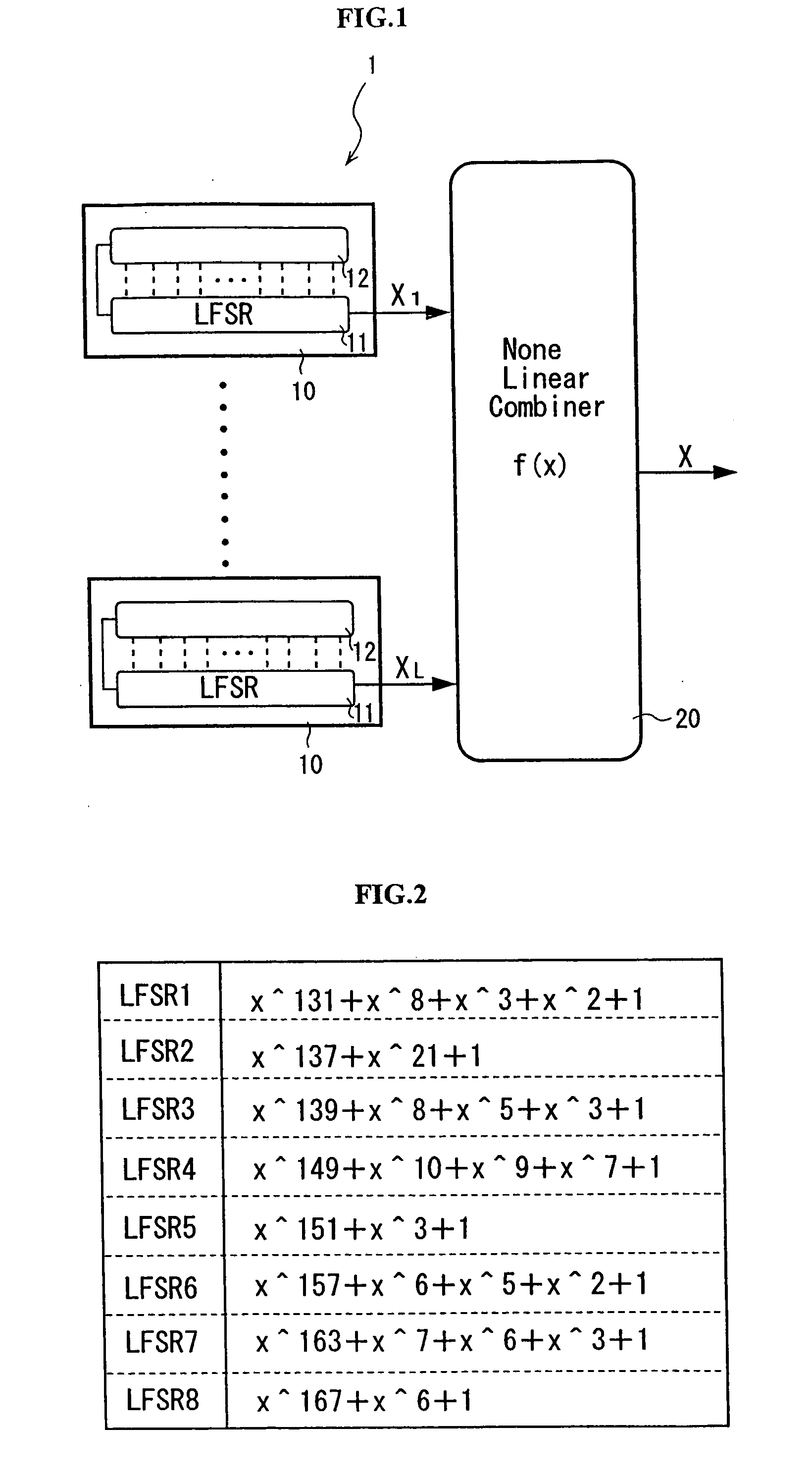
[0126]FIG. 1 is a view explaining a pseudo-random number generator 1 according to the first embodiment of the invention. In the embodiment, a nonlinear-combiner-type pseudo-random number generator 1 is explained as an example of the pseudo-random number generator.

[0127] The pseudo-random number generator 1 has an initial state value setting part (not shown) for setting an initial state value based on a secret key which is given by a user, plural pseudo-random number generating parts 10 for generating pseudo-random numbers based on the initial state value received from the initial state value setting part, and a nonlinear conversion part 20 which is connected to each of output sides of these plural pseudo-random number generating parts 10 and nonlinearly converses the pseudo-random numbers outputted from each of the pseudo-random number generating parts 10.

[0128] The initial state value ...

second embodiment

[0154] Subsequently, the second embodiment of the present invention is explained by referring to the drawings.

[0155]FIG. 4 is a view schematically explaining function of a pseudo-random number generator 1 according to the second embodiment of the invention. The pseudo-random number generator 1 of the embodiment is a nonlinear-combiner-type pseudo-random number generator 1 materiarized by running a pseudo-random number program on computer hardware. In the embodiment, the generator is explained only in the case of using in an encryption device (see Description of the Related Art), and the explanation is omitted in the case of using in a decryption device because the explanation is similar to that in the encryption device.

[0156] The pseudo-random number generator 1 has a random number bit string outputting part 50, a random number bit string amplifying part 60, and a nonlinear conversion part 80, as shown in FIG. 4. The random number bit string outputting part 50 is provided with a (...


PUM


Abstract

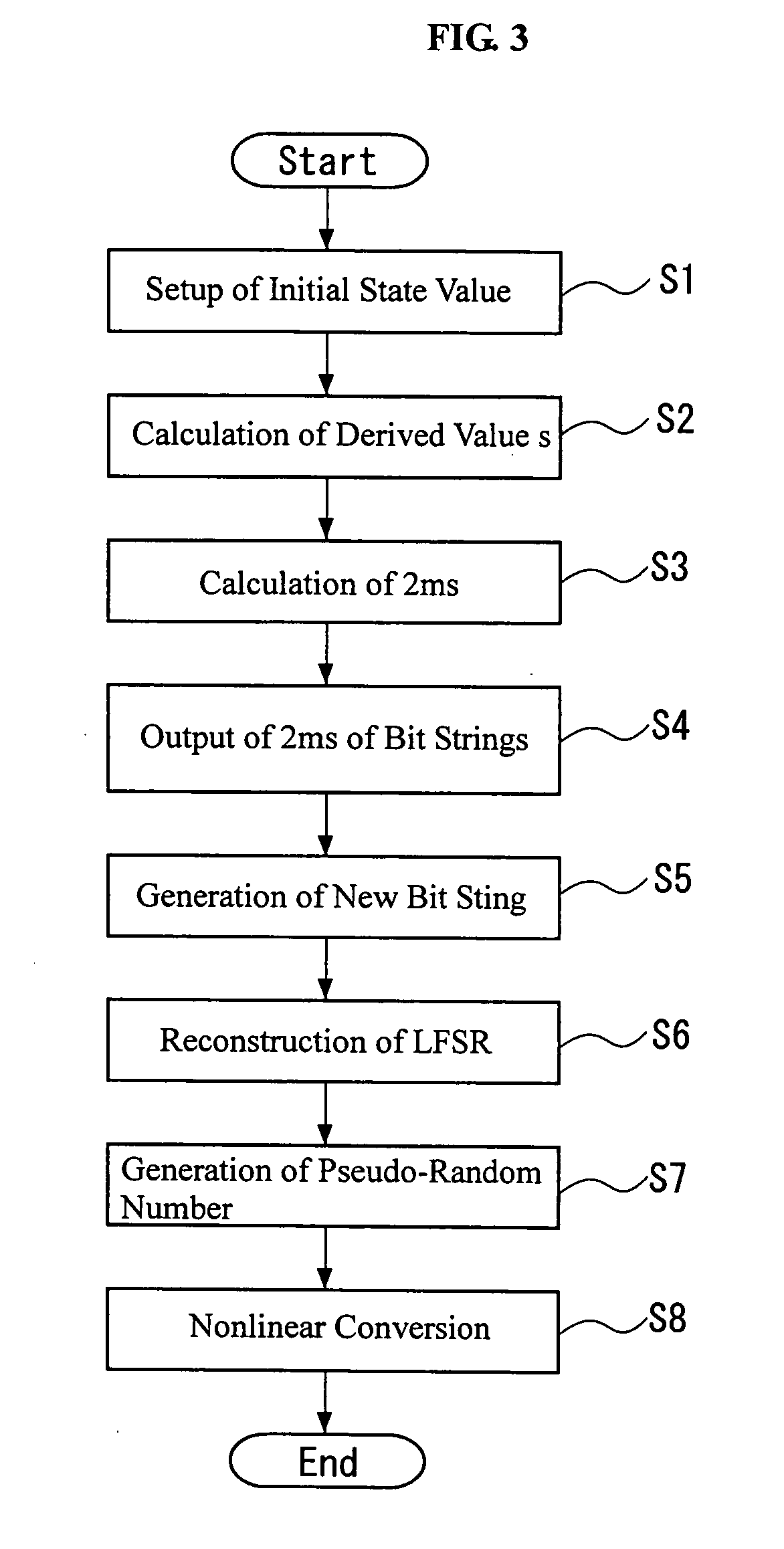
A bit string obtained by sampling, every the number s, bits of a bit string whose output sequence is M sequence, when the bit number per one cycle of the M sequence is prime to the derived value, constitutes M sequence of a linear feedback shift register having other construction. Further, the linear feedback shift register can be determined from bits corresponding to at least two cycles by Berlekamp-Massay algorithm, whereby the linear feedback shift register 11 can be easily and dynamically reconstructed based on the initial state value.

Description

BACKGROUND OF INVENTION [0001] 1. Field of the Invention [0002] The present invention relates to a method for generating pseudo-random numbers useful in cryptography communication and digital signature, a pseudo-random number generator and a program for generating pseudo-random numbers. [0003] 2. Description of the Related Art [0004] Conventionally, in case information communication is carried out through wire or radio, the information is transmitted after its encryption so as not to leak its content to third party. Systems of the encryption include a stream cipher system. In the stream cipher system, transmission and reception sides generate the same pseudo-random numbers as each other, and the transmission side prepares a bit string of a cryptogram by using a bit string of the pseudo-random numbers and a bit string of a plaintext to transmit the bit string as cryptogram to the reception side, while the reception side receives the cryptogram of bit string and decrypts the bit strin...

Claims


Application Information

Patent Timeline
Patent Type & Authority Applications(United States)
IPC IPC(8): H04L9/00G06F7/58G09C1/00H04L9/22
CPCG06F7/582H04L9/0668G06F7/584
Inventor MORII, MASAKATUSHIRAISHI, YOSHIAKI
Owner KOBAYASHI AKIRA
Learn More