
Organic photoreceptor, image forming apparatus, image forming method and image forming unit

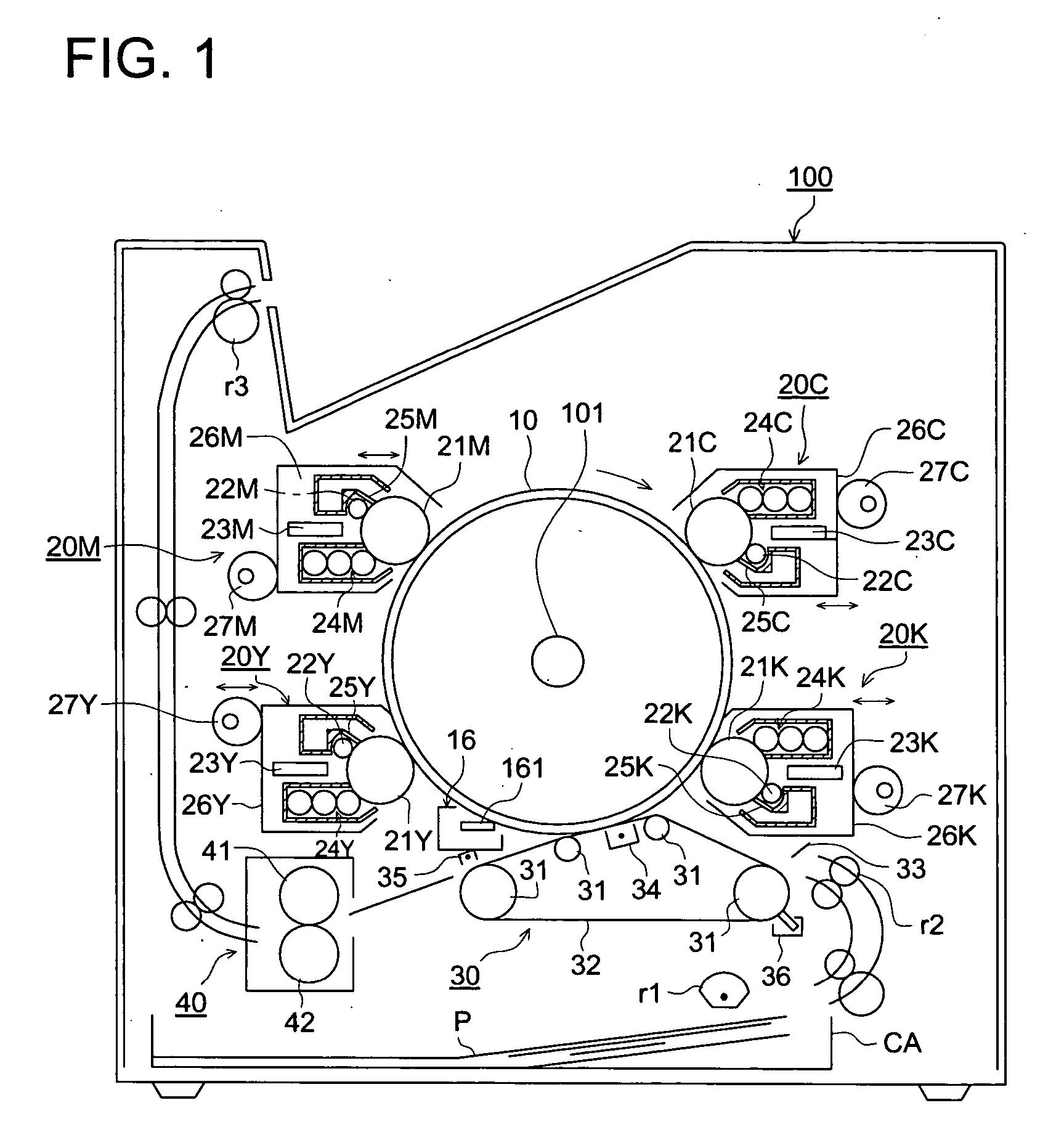
an image forming apparatus and organic technology, applied in the direction of electrographic process, instruments, corona discharge, etc., can solve the problems of color shading or color misalignment, organic photoreceptors are not fully sufficient solutions for photoreceptor durability, increase in image defects such as fogging and black spots, etc., to suppress the degradation of image density, improve the durability of organic photoreceptors of thin layer type, and improve image sharpness

Inactive Publication Date: 2006-02-23
KONICA MINOLTA INC
View PDF5 Cites 0 Cited by
  • Summary
  • Abstract
  • Description
  • Claims
  • Application Information

AI Technical Summary

Benefits of technology

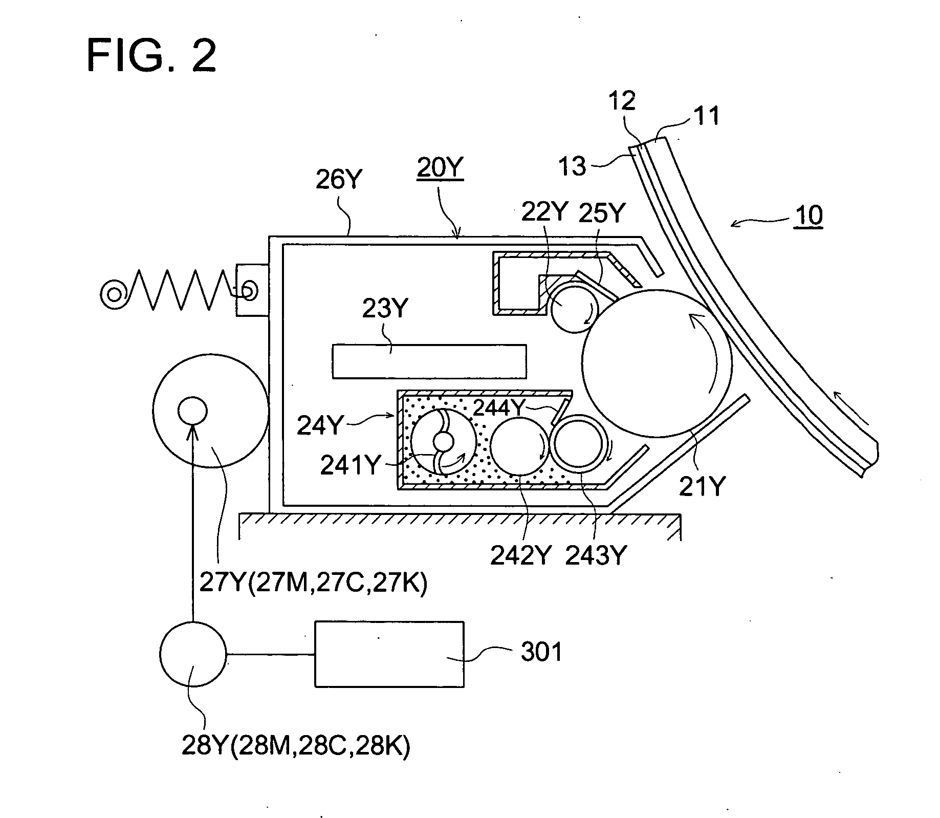
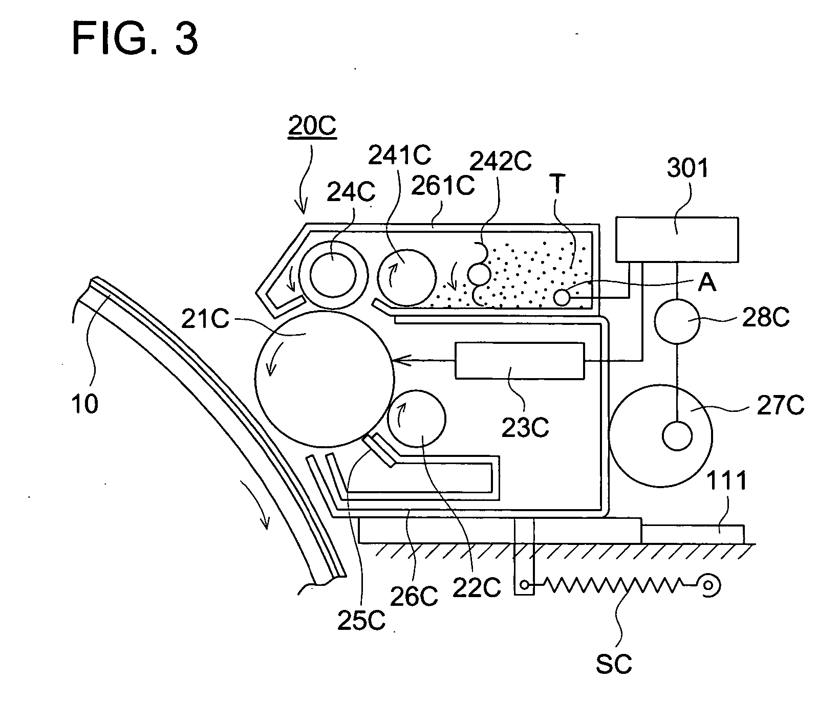
[0013] An object of the present invention is to provide an organic photoreceptor having the following features. Firstly, the organic photoreceptor improves durability of thin layer type organic photoreceptors. Secondarily, the organic photoreceptor suppresses degradation of image density and occurrence of fogging and image defects of black spots and provides a sharper image, even after the layer thickness is decreased by abrasion over long-term use. Finally, when the organic photoreceptor is used in a tandem type image forming apparatus, the organic photoreceptor provides a durable image forming unit which gives high resolution dot images, as well as an image forming apparatus and image forming method which gives sharp images.
[0014] The present invention has been achieved by the finding that, by lowering the layer thickness dependence of sensitivity of an organic photoreceptor, only a small change in properties of an electrophotographic image forming system, for example, sensitivity and high resolution images, were obtained even after the layer thickness of the organic photoreceptor was decreased and, also, the above mentioned problem in tandem type image forming system was resolved.

Problems solved by technology

However, since the tandem method utilizes a separate photoreceptor for each color, it easily results in color shading or color misalignment unless the ability of each photoreceptor is stable.
However, these cited organic photoreceptors are not fully sufficient solutions with respect to durability of the photoreceptor.
Specifically, charging performance and sensitivity of an organic photoreceptor are in general greatly dependent on the layer thickness, and a decrease in the layer thickness due to repeated use tends to cause an increase in image defects such as fogging and black spots.
Specifically, in an organic photoreceptor with a thin photoreceptive layer, loading conditions of charging potential in the electrostatic latent image forming step tend to increase the electric field intensity per unit layer thickness, which easily causes the problems mentioned above.
However, a thicker layer of the photoreceptor may result in a decrease in thin line reproducibility, and a lower abrasive cleaning system may cause toner filming on the photoreceptor surface due to a insufficient cleaning, and new image defects may occur.
These problems tend to occur especially in a high resolution and high speed tandem type image forming system.

Method used


Image

  • Organic photoreceptor, image forming apparatus, image forming method and image forming unit
  • Organic photoreceptor, image forming apparatus, image forming method and image forming unit
  • Organic photoreceptor, image forming apparatus, image forming method and image forming unit

Examples


example 1

Preparation of Photoreceptors Groups 1-3

[0285] The following liquid coating composition was prepared and coated on a cleaned cylindrical aluminum base member with a diameter of 30 mm, by a dip coating method, to form an under coat layer.

[0286] An under coat layer having organic segment component, inorganic segment component and antioxidation stractural component of a thickness of 4.0 μm was prepared as follows: [0287] (i) The following materials were mixed and well stirred:

[0288] Solution of Organic Segment Component A

(Solution for vinyl polymer A having a hindered100 partsamine group and being Cyril modified)Methyl trimethoxy silane 70 partsDimethyl dimethoxy silane 30 partsMinute particles (Anatase type titanium oxide(number100 partsaverage particle diameter of primary particles: 35 nm, primarysurface treantment: silica-alumina treatment and secondarysurface treatment: methylhydrodien poly siloxyane treatment)butyl alcohol100 partsbutylcellosolve 75 partsdi-i-propoxy ethyl a...


PUM

PropertyMeasurementUnit
surface potentialaaaaaaaaaa
thicknessaaaaaaaaaa
thicknessaaaaaaaaaa

Abstract

An organic photoreceptor comprising a conductive support on which a charge generating layer and a charge transporting layer are stacked in that order, wherein a changing rate of an exposure energy change (E600 / 100)n is not larger than 0.01 (μJ / (cm2·μm)) when a thickness of the charge transporting layer n decreases from 20 μm to 15 μm and when a surface potential of the organic photoreceptor varies from −600 V to −100 V, the changing rate of the exposure energy change (E600 / 100)n being defined by the following formula: ((E600 / 100)20−(E600 / 100)15) / (20−15)

Description

TECHNICAL FIELD [0001] The present invention related to an organic photoreceptor, and image forming apparatus, an image formation method and an image formation unit used for copying machines, printers and facesimile apparatuses. BACKGROUND [0002] As one of color image formation methods, an image formation method so-called a tandem method has been known, in which color toner image are formed on separate photoreceptors, each of which has a different single color, and the images are superimposed on an intermediate transfer member or on a recording member. (Patent Document 1). [0003] However, since the tandem method utilizes a separate photoreceptor for each color, it easily results in color shading or color misalignment unless the ability of each photoreceptor is stable. [0004] Alternatively, in order to increase quality of color images, a technology to form minute dot images has been developed, in which a minute latent image is formed on an organic photoreceptor using an exposure ligh...

Claims


Application Information

Patent Timeline
Patent Type & Authority Applications(United States)
IPC IPC(8): G03G5/047
CPCG03G5/047G03G5/0517G03G5/0521G03G5/0564G03G9/0819G03G5/0614G03G5/0672G03G5/144G03G5/0578
Inventor ITAMI, AKIHIKO
Owner KONICA MINOLTA INC
Learn More