Efficient bypass valve for multi-stage turbocharging system

a bypass valve and turbocharging system technology, applied in the direction of valve operating means/release devices, machines/engines, mechanical devices, etc., can solve the problems of expanding and losing potential energy

Inactive Publication Date: 2006-03-02
UNITED STATES OF AMERICA
View PDF19 Cites 58 Cited by
  • Summary
  • Abstract
  • Description
  • Claims
  • Application Information

AI Technical Summary

Benefits of technology

[0014] According to an embodiment of the invention, a turbocharger system is provided, comprising a high-pressure turbine having an inlet and an outlet, a bypass channel having a first end in fluid communication with the inlet of the high-pressure turbine and a second end in fluid communication with the outlet of the high-pressure turbine and configured to allow bypass of flow around the high-pressure turbine, and a low pressure turbine having an inlet in fluid communication with the outlet of the high-pressure turbine a...

Problems solved by technology

As the gas in the exhaust stream loses pressure, it expands and loses potential energy.
In a turbocharged internal combustion engine system, the wide range of speed and power output levels...

Method used


Image

  • Efficient bypass valve for multi-stage turbocharging system
  • Efficient bypass valve for multi-stage turbocharging system
  • Efficient bypass valve for multi-stage turbocharging system

Examples


Embodiment Construction

[0029] In the following description, certain specific details are set forth in order to provide a thorough understanding of various embodiments of the invention. However, one skilled in the art will understand that the invention may be practiced without these details.

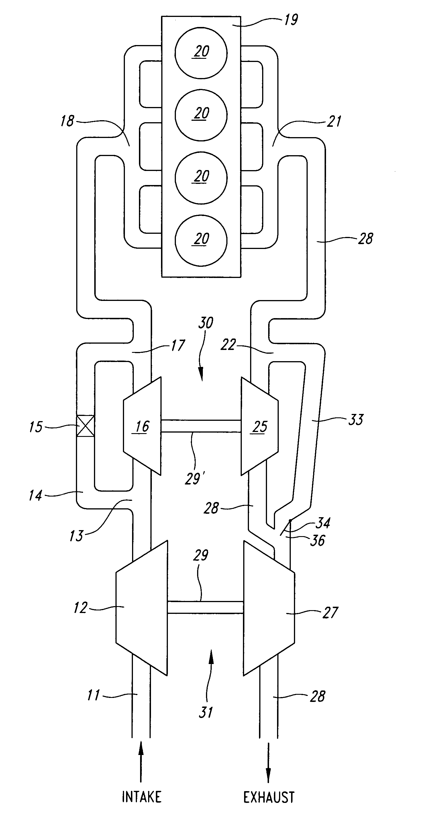
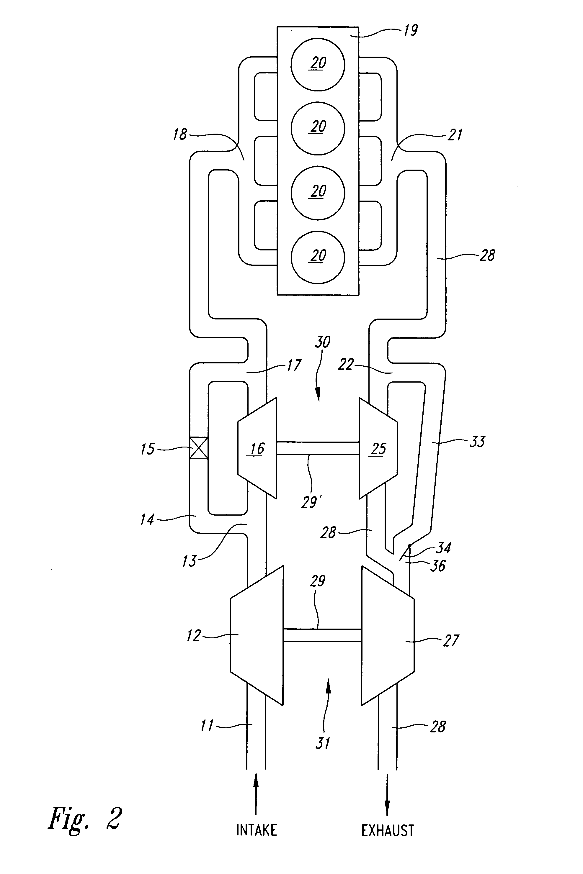
[0030] Embodiments of the invention described hereafter deal primarily with more efficient recovery of the energy of the exhaust gas stream of an internal combustion engine.

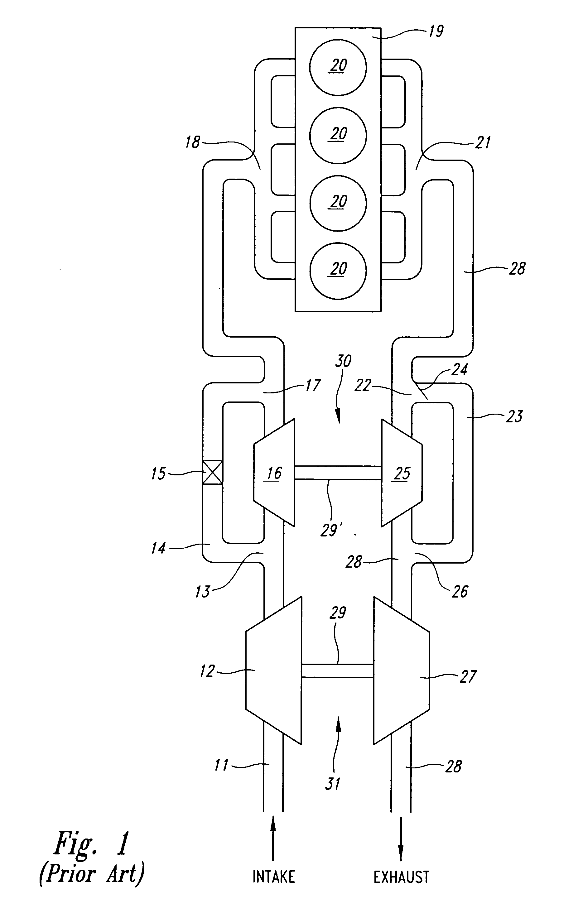
[0031] Referring again to FIG. 1, as previously explained, there is a drop in pressure across the high-pressure turbine 25 as the exhaust is expanded over the turbine while the turbine captures energy from the exhaust flow. Unfortunately, an equal drop in pressure occurs in the exhaust that flows between ports 22 and 26 on the bypass line 23, all of which is unrecovered exhaust energy. Most of this pressure drop occurs at the wastegate 24. The inventors have recognized that this pressure drop in the bypass channel 23 represents a loss of useful ene...


PUM


Abstract

A turbocharger system includes first and second turbines arranged such that exhaust gas passes through the first turbine then the second turbine. A bypass channel is configured such that exhaust gas entering the channel passes only through the second turbine. A valve positioned in the bypass channel regulates the flow of gas therethrough. The valve accelerates a stream of gas and focuses the stream toward the second turbine such that a large part of the added velocity of the stream is preserved as it enters the second turbine. Operation of the valve may be controlled so as to maintain the valve in a closed position while exhaust gas pressure above the first turbine pressure is below a first threshold, to progressively open the valve as the pressure increases above the first threshold, and to maintain the valve in a full-open position while the pressure is above a second threshold.

Description

CROSS-REFERENCE TO RELATED APPLICATION [0001] This application claims the benefit under 35 U.S.C. § 119(e) of U.S. Provisional Patent Application No. 60 / 605,898 filed Aug. 31, 2004, where this provisional application is incorporated herein by reference in its entirety.BACKGROUND OF THE INVENTION [0002] 1. Field of the Invention [0003] The invention disclosed herein is generally related to turbocharger systems for internal combustion engines, and in particular, to multi-stage turbochargers having bypass systems for diverting exhaust gas flow around a first turbine. [0004] 2. Description of the Related Art [0005] Turbocharging systems, such as for use with internal combustion engines, are well known in the art. A turbocharger comprises an exhaust gas turbine coupled to an intake charge compressor. The turbine operates by receiving a stream of exhaust gas from an internal combustion engine and converting a portion of the energy in the exhaust gas stream into mechanical energy by passin...

Claims


Application Information

Patent Timeline
IPC IPC(8): F02D23/00F02B33/44
CPCF01D17/14F02B37/013F02B37/18F02B37/183F02B37/004F05B2220/40F16K1/12F16K3/0209Y02T10/144F02B37/22Y02T10/12
Inventor GRAY, CHARLES L. JR.HAUGEN, DAVID JAMES
Owner UNITED STATES OF AMERICA
Why Eureka
Try Eureka