Heater-contained gas sensor operation starting method and operation stopping method, and operating method

a gas sensor and heater technology, applied in the direction of electric control, instruments, specific gravity measurement, etc., can solve the problems of deterioration, damage, and easy condensation of off-gas moisture content, and achieve the effect of suppressing the occurrence of missed detection

Active Publication Date: 2006-03-02
SHIGA INT PATENT OFFICE +1
View PDF14 Cites 29 Cited by
  • Summary
  • Abstract
  • Description
  • Claims
  • Application Information

AI Technical Summary

Benefits of technology

[0054] According to the aforementioned method of operating a gas sensor with a built-in heater, the gas sensor with a built-in heater can be started in a state wherein the occurrence of condensation inside the gas detection chamber has been prevented, while suppressing the occurrence of missed detection and the like with respect to the hydrogen gas flowing in the off-gas pipe. Furthermore, the occurrence of condensation inside the gas detection ch

Problems solved by technology

In this case, deterioration of, and damage to, the hydrogen detector may occur.
Therefore there is the problem that the moisture content of the off-gas readily condenses.
Furthermore, for example, when the gas-contact combustion-type hydrogen detector is provided, particularly when provided in the exhaust system on the oxygen elec

Method used


Image

  • Heater-contained gas sensor operation starting method and operation stopping method, and operating method
  • Heater-contained gas sensor operation starting method and operation stopping method, and operating method
  • Heater-contained gas sensor operation starting method and operation stopping method, and operating method

Examples


first embodiment

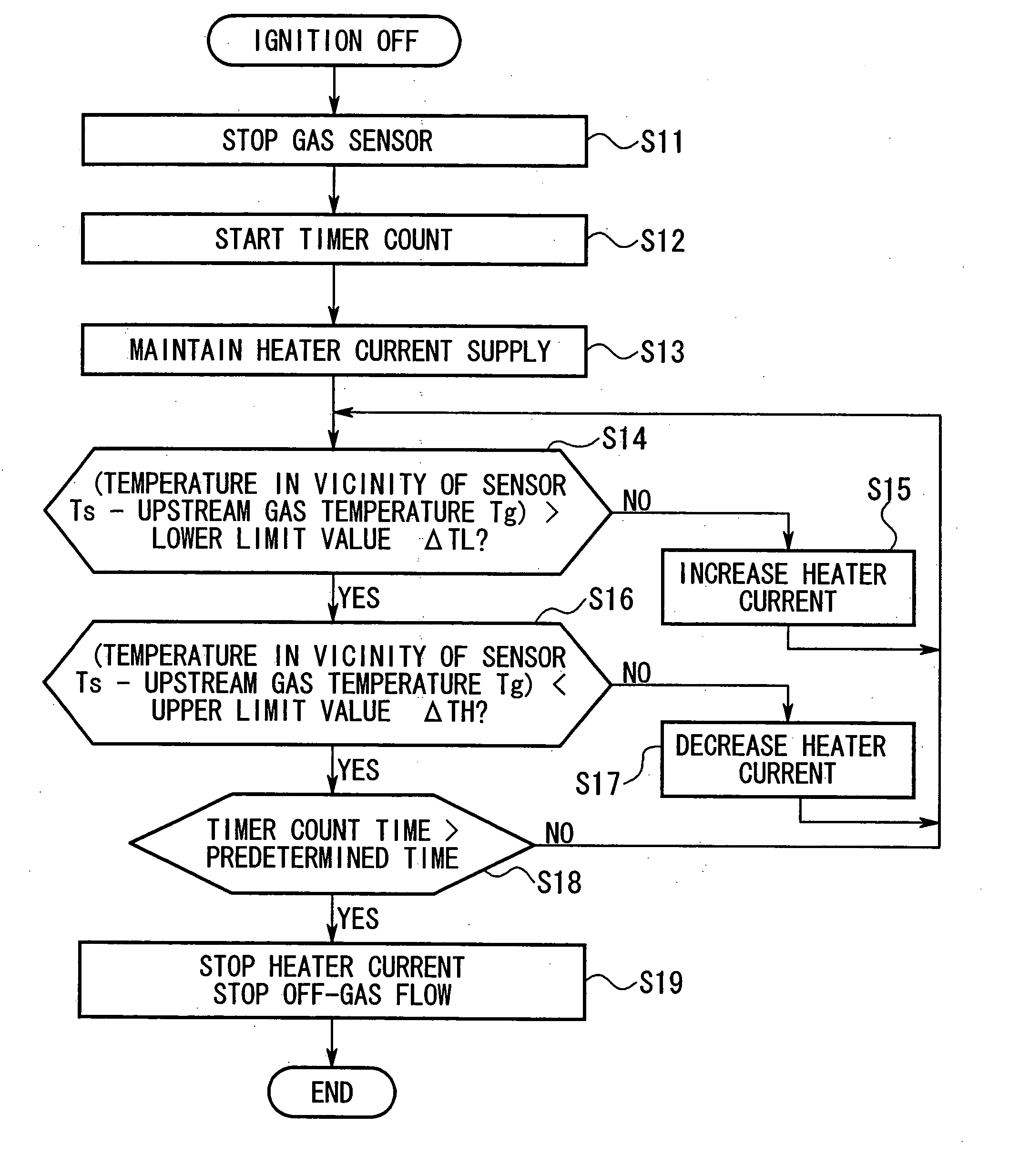
[0194] As described above, according to the method of starting a gas sensor with a built-in heater in the present invention, by starting operation of the heater prior to starting operation of the gas sensor with a built-in heater, the gas sensor with a built-in heater can be started in a state wherein the occurrence of condensation has been prevented.

second embodiment

[0195] Moreover, according to the method of starting a gas sensor with a built-in heater in the present invention, by setting the temperature inside the gas detection chamber higher than the predetermined threshold temperature, the gas sensor with a built-in heater can be started in a state wherein the occurrence of condensation has been reliably prevented.

third embodiment

[0196] Furthermore, according to the method of starting a gas sensor with a built-in heater in the present invention, by starting the flow of cathode off-gas of the fuel cell to the flow tube at or after operation of the gas sensor with a built-in heater, the occurrence of missed detection and the like with respect to the hydrogen gas within the cathode off-gas can be reliably prevented.


PUM


Abstract

A control apparatus for a gas sensor with a built-in heater is provided which can prevent damage to, deterioration of, and reduction in accuracy of detection of, a gas sensor. When an ignition switch is turned ON, supply of electricity to a heater 27 starts, and when the temperature in the vicinity of a gas sensor 15 (gas temperature of gas detection chamber 24) Ts becomes greater than a predetermined temperature #Ti at start, or when a predetermined electricity supply time after start of supply of electricity to the heater 27 has elapsed, the gas sensor 15 is started. The flow of off-gas is started simultaneously with starting of the gas sensor 15, or after starting. When the ignition switch is turned OFF, the flow of off gas is stopped, and the supply of electric power to the gas sensor 15 is stopped. In a state where a temperature difference ΔT between the gas temperature Ts inside the gas detection chamber 24, and an upstream gas temperature Tg is maintained within a predetermined range, the supply of electricity to the heater 27 is stopped after a predetermined time has elapsed after operation of the gas sensor 15 is stopped.

Description

TECHNICAL FIELD [0001] The present invention relates to a method of starting, stopping, and operating a gas sensor with a built-in heater, in particular to a method of starting, stopping, and operating, a gas sensor with a built-in heater to prevent condensation on a detecting element and on a temperature compensation element of a detector section. [0002] Priority is claimed on Japanese Patent Application No. 2002-139094, the content of which is incorporated herein by reference. BACKGROUND OF THE INVENTION [0003] Conventionally, for example, a solid high-polymer membrane-type fuel cell is provided with a cell wherein a solid high-polymer electrolytic membrane is sandwiched between a fuel electrode and an oxygen electrode, and a plurality of cells are configured in a layered stack (hereafter referred to as a fuel cell). Hydrogen is supplied to the fuel electrode as fuel, and air is supplied to the oxygen electrode as oxidant, and oxygen ions produced at the fuel electrode due to a ca...

Claims


Application Information

Patent Timeline
IPC IPC(8): G01N27/26G01N27/16G01N33/00
CPCG01N27/16G01N33/0029G01N33/0062G01N33/006G01N33/005
Inventor SASAKI, TAKASHIABE, HIROYUKIEGUCHI, TSUYOSHISUZUKI, AKIHIRO
Owner SHIGA INT PATENT OFFICE
Why Eureka
Try Eureka