[0007] An object of the instant invention is to provide a heated hand grip that can be easily installed on a ski pole or other tubular object. Another object of the instant invention is to provide a heated hand grip that provides a comfortable, cushioned grip. Other objects of the instant invention are to provide an electrically heated hand grip that is waterproof, easy to manufacture, lightweight and reliable.
[0009] In a preferred embodiment of the instant invention, the outer surface of the central core is generally smooth and a wire-wound heating element (including a fiberglass material backing and an
electrical conductor) is wrapped around and attached to the
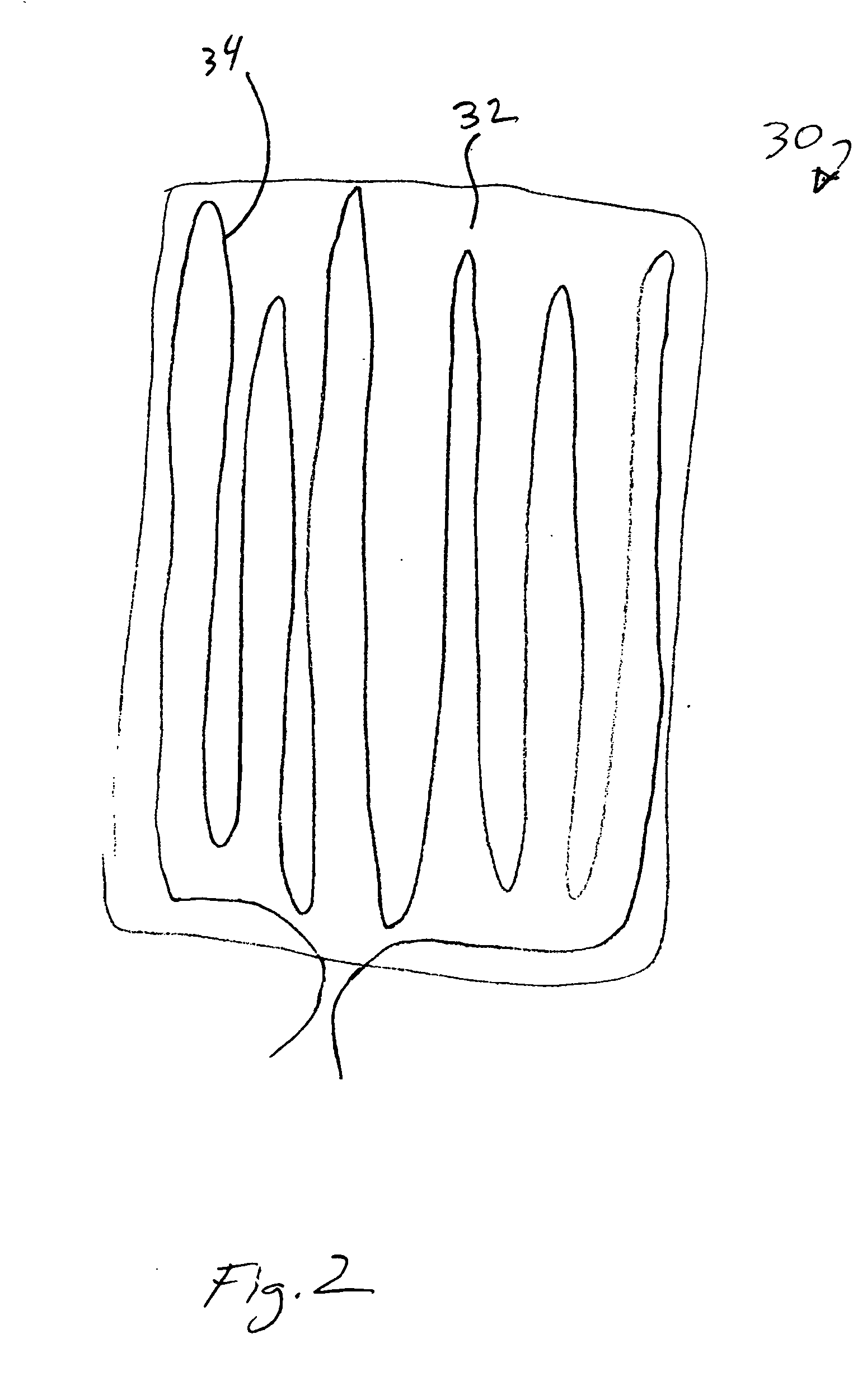
smooth surface. In an alternative embodiment, the outer surface of the central core includes
helical grooves in which a wire heating element is positioned. The heating element is connected to the PCB to be turned on and off by the
control switch. The central core is manufactured of a relatively rigid material, such as
high density polypropylene (HDPP). In a preferred embodiment the central core is made of a composite of HDPP which includes approximately 30% glass. The glass increases the insulating characteristics of the central core so as to minimize heat drain from the heating element to the bore of the central core and through the pole to which the grip is attached.
[0010] The one-piece pour-over outer housing forms a shell around the outer surface of the central core of the hand grip. The housing is made of a rubber, lower density
polypropylene, or other material suitable to provide the amount of
cushioning desired for the hand grip. The material, in a fluid state, is poured over the central core after the heating element is positioned (either over the
smooth surface or in the grooves of the core), and the fluid is allowed to solidify. In the embodiment in which the heating element comprises a
fiber glass backing material and attached conductor, the fluid of the housing pour-over will soak through the fiberglass backing to bond with the central core. The thicknesses of the walls of the outer housing are minimized to increase the efficiency of heat conduction from the heating element to the outer surface of the housing. At the same time enough wall thickness is provided to provide adequate
cushioning for the grip when held by a user.
[0011] In a preferred embodiment, appropriate material compositions and thickness are selected to allow the outer surface of the outer housing to reach and maintain a temperature of 104° F. at an
environmental temperature as low as −20° F. A temperature sensor (or temperature
limiter switch) is located between the outer surface of the central core and the inner surface of the housing. The temperature sensor is connected electrically to the PCB to cause the heating element to be deenergized when the temperature exceeds the 104° F. level. In addition, the temperature sensor will cause the heating element to reenergize when the temperature drops below a minimum level, such as 95° F. It will be appreciated that two or more separate temperature switches can also be utilized to maintain the temperature in the desired operating range.
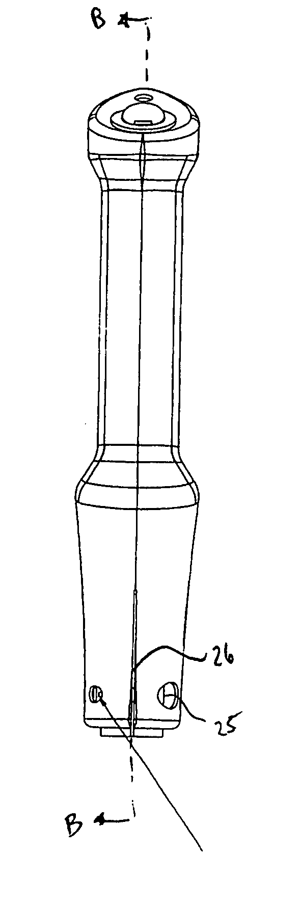
[0012] In a preferred embodiment of the instant invention, a split
bushing is utilized to hold the ski pole within the bore of the central core. In addition, the lower portions of the central core and the outer housing, in which the bushing is to be located, include a lateral slit. The split bushing allows the ski pole to be easily inserted into the bushing by reducing the frictional forces exerted on the outer surface of the pole by the inner surface of the bushing as the split in the bushing allows the walls of the bushing to deform and separate from each other as the pole is inserted. Likewise, the lateral slit in the core / housing allows the walls of the core / housing to separate from each other as the bushing is inserted into the bore, allowing the bushing to be inserted with a minimal amount of effort. Once the ski pole is inserted in the bushing the bushing then is inserted in the bore of the central core (to which the outer housing has already been poured over). A screw is then inserted through the housing / core and tightened to clamp the housing / core around the bushing, which in turn clamps the bushing around the pole. This provides a tight frictional fit between all of the components such that the pole cannot be released from the hand grip without loosening the screw. In a preferred embodiment, multiple bushings having various inner diameters are provided with each hand grip to allow the hand grip to be installed on ski poles of varying common outer diameters. For example, common outer diameters for ski poles include, but are not limited to, 13 mm and 11 mm. The actual diameters for a ski pole shaft will vary slightly between manufacturers and materials used for the pole. Nevertheless, the construction of the instant invention including the split bushing, core slit and screw allows for a tight frictional engagement regardless of slight variations in pole diameters. Therefore, it is not required that the bushing of the instant invention have an inner
diameter that corresponds exactly to the outer
diameter of the pole. Bushings of various other inner diameters can be utilized in connection with the instant invention to permit installation on virtually any tubular object in which inclement conditions affect warmth and comfort, such as alpine poles, hiking poles,
cross country poles, shovels, paddles, etc. Furthermore, it will be appreciated that the bushing can be eliminated in cases in which the inner
diameter of the bore in the central core corresponds to the outer diameter of the tubular object to which the
handle is being attached, and multiple size options are not desired. For example, the hand grip of the instant invention can be designed to be the
handle for a
snow shovel. In such an arrangement, slight modification of the hand grip discussed above will be made to retain the battery in position without the bushing.

