Hydrodynamic pressure bearing spindle motor

a spindle motor and hydrodynamic pressure technology, applied in the direction of elastic bearings, bearing unit rigid support, instruments, etc., can solve the problems of reducing the total generating noise and vibration, and reducing the quantity of lubricating oil, so as to reduce axial loss, improve axial bearing capacity, and maximize the effect of generating dynamic pressur

Inactive Publication Date: 2006-03-02
SAMSUNG ELECTRO MECHANICS CO LTD
View PDF6 Cites 10 Cited by
  • Summary
  • Abstract
  • Description
  • Claims
  • Application Information

AI Technical Summary

Benefits of technology

[0022] Therefore, the present invention has been made in view of the above problems, and it is an object of the present invention to provide a hydrodynamic pressure bearing spindle motor, in which dimensions of portions, of slide planes between a stationary member and a rotary member, for generating dynamic pressure are maximized, thereby improving axial bearing capacity and reducing axial loss, thus minimizing power consumption.

Problems solved by technology

Generally, there is friction between a motor, employing a ball bearing, and a shaft, thereby generating noise and vibration.
Such vibration is refereed to as NRRO (Non Repeatable Run Out), and serves as an obstacle in increasing the density of tracks of a hard disk.
When the spindle motor 1 is driven, frictional resistance at the dynamic pressure non-generating portion is increased, thereby causing axial loss.
However, the total quantity of the lubricating oil is decreased due to the leakage of the oil, thereby generating noise and vibration, and reducing the lifespan of the spindle motor 1.

Method used


Image

  • Hydrodynamic pressure bearing spindle motor
  • Hydrodynamic pressure bearing spindle motor
  • Hydrodynamic pressure bearing spindle motor

Examples


first embodiment

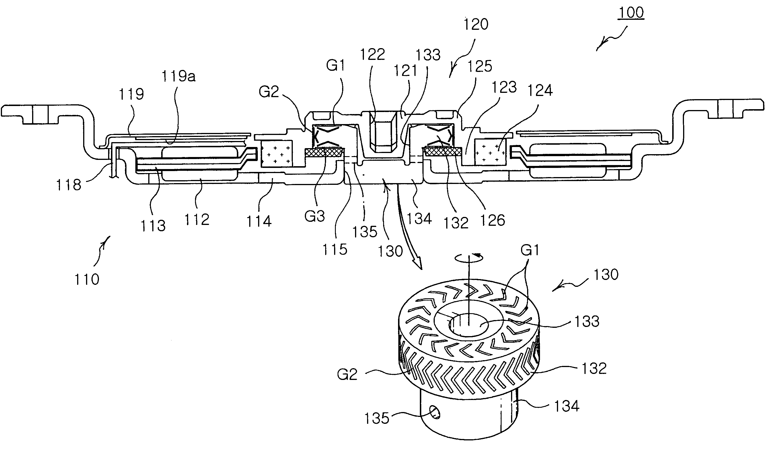
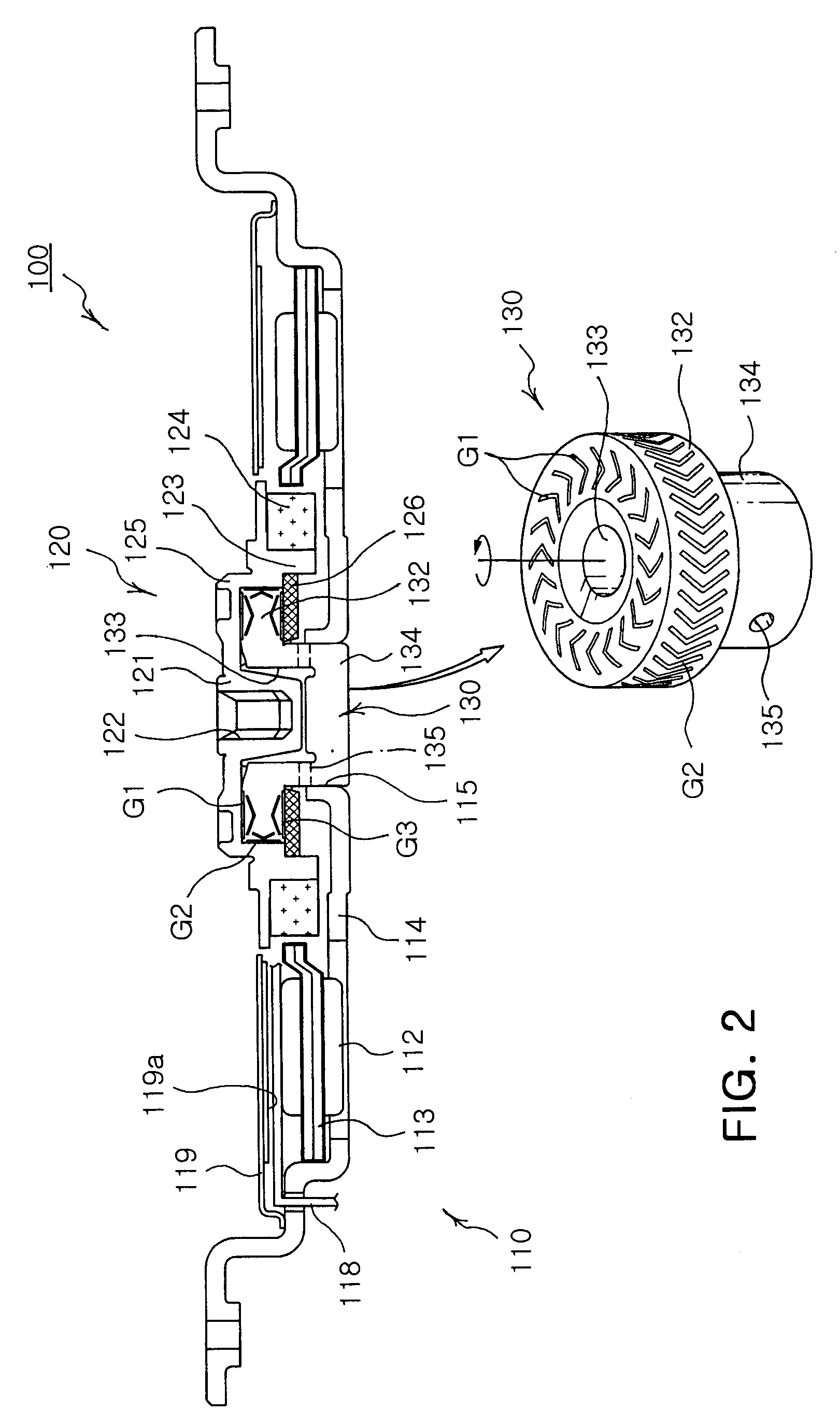
[0093]FIGS. 5a, 5b, and 5c illustrate upper and lower sealing and oil-storing units of the hydrodynamic pressure bearing spindle motor in accordance with the present invention. The upper sealing and oil-storing unit 140a and the lower sealing and oil-storing unit 140b, which prevent lubricating oil, supplied to the dynamic pressure generating grooves G1, G2, and G3 formed in slide planes of the sleeve 130 for generating dynamic pressure due to the relative rotation of the rotary structure against the stationary structure, from flowing out, and store the lubricating oil, are selectively or simultaneously formed on the sleeve 130.

[0094] The upper sealing and oil-storing unit 140a is formed between the horizontal upper inner surface of the hub 125 and an inclined portion 141 sloping downwardly to the inner diameter to be gradually distant from the upper surface of the sleeve 130 so that the upper sealing and oil-storing unit 140a prevents the lubricating oil, supplied to the upper dyna...

second embodiment

[0115]FIGS. 9a, 9b, and 9c illustrate upper and lower sealing and oil-storing units of the hydrodynamic pressure bearing spindle motor in accordance with the present invention. The upper sealing and oil-storing unit 240a and the lower sealing and oil-storing unit 240b, which prevent lubricating oil, supplied to the dynamic pressure generating grooves G1, G2, and G3 formed in slide planes of the sleeve 230 for generating dynamic pressure due to the relative rotation of the rotary structure against the stationary structure, from flowing out, and store the lubricating oil, are selectively or simultaneously formed on the sleeve 230.

[0116] The upper sealing and oil-storing unit 240a is formed between the horizontal upper inner surface of the hub 225 and an inclined portion 241 sloping downwardly to the inner diameter to be gradually distant from the outer surface of the large outer diameter portion 232 of the sleeve 230 so that the upper sealing and oil-storing unit 240a prevents the lub...


PUM


Abstract

A spindle motor, having a hydrodynamic pressure bearing, including: a stator including a core, on which at least one winding coil is wound, and a base provided with a central hole formed through the central area of the main body thereof so that the core is placed on the upper surface thereof; a rotor including a hub having a magnet formed on the outer circumference thereof to correspond to the winding coil leaving a designated interval with the winding coil, and a stop ring installed on the inner circumference of the hub; and a sleeve, for supporting the rotation of the rotor, including at least one dynamic pressure generating groove formed on the outer surface thereof correspondingly contacting the inner circumference of the hub and the stop ring, and a hub receiving hole formed through the central area of the main body thereof assembled with the central hole of the base.

Description

RELATED APPLICATIONS [0001] The present application is based on, and claims priority from, Korean Application Number 2004-69660, filed Sep. 1, 2004, the disclosure of which is hereby incorporated by reference herein in the entirety. BACKGROUND OF THE INVENTION [0002] 1. Field of the Invention [0003] The present invention relates to a spindle motor having a hydrodynamic pressure bearing, and more particularly to a hydrodynamic pressure bearing spindle motor, which maximizes the dimensions of dynamic pressure generating portions formed on slide planes between a stationary member and a rotary member, thereby improving axial rigidity, reducing axial loss to achieve low power consumption, being rotated at a high degree of precision, reducing the number of required components to be decreased in terms of size, and reducing production costs. [0004] 2. Description of the Related Art [0005] Generally, there is friction between a motor, employing a ball bearing, and a shaft, thereby generating...

Claims


Application Information

Patent Timeline
Patent Type & Authority Applications(United States)
IPC IPC(8): H02K5/16H02K7/08F16C27/00
CPCF16C17/107H02K7/086H02K5/1677F16C33/107F16C2370/12G11B21/02
Inventor SON, DONG KILLIM, TAE HYEONGLEE, TA KYOUNG
Owner SAMSUNG ELECTRO MECHANICS CO LTD
Why Eureka
Try Eureka