
Three-point contact thrust ball bearing and design method

A thrust ball bearing and three-point contact technology, applied in the field of thrust bearings, can solve the problems of reduced service life of thrust ball bearings, large runout, and high bearing assembly

Inactive Publication Date: 2010-07-14
HENAN SANWEI HEAVY IND
View PDF11 Cites 4 Cited by
  • Summary
  • Abstract
  • Description
  • Claims
  • Application Information

AI Technical Summary

Problems solved by technology

[0002] At present, the commonly used thrust ball bearing is composed of a shaft ring, a seat ring, steel balls and a cage. The steel ball and the cage are arranged between the shaft ring and the seat ring, and the steel ball rotates between the shaft ring and the seat ring. There are arc-shaped grooves on both the ring and the seat ring, and the radius of the arc is slightly larger than the radius of the steel ball. The thrust ball bearing of this structure only bears axial load, not radial load, and each steel ball and shaft There is only one contact point between the ring and the seat ring, and the axial load capacity of the bearing is limited; when the size of the thrust ball bearing is limited and it needs to bear a large axial load, the service life of the thrust ball bearing will be greatly reduced
Moreover, the processing accuracy of the thrust ball bearing is difficult to guarantee, especially the coaxiality of the channel between the shaft ring and the seat ring. Since the processing accuracy of the channel cannot be guaranteed, the assembly of the whole set of bearings is high and the runout is large, which is difficult to apply to In high-precision processing equipment

Method used


Image

  • Three-point contact thrust ball bearing and design method
  • Three-point contact thrust ball bearing and design method
  • Three-point contact thrust ball bearing and design method

Examples


Embodiment Construction

[0016] The present invention will be described in further detail below in conjunction with the accompanying drawings.

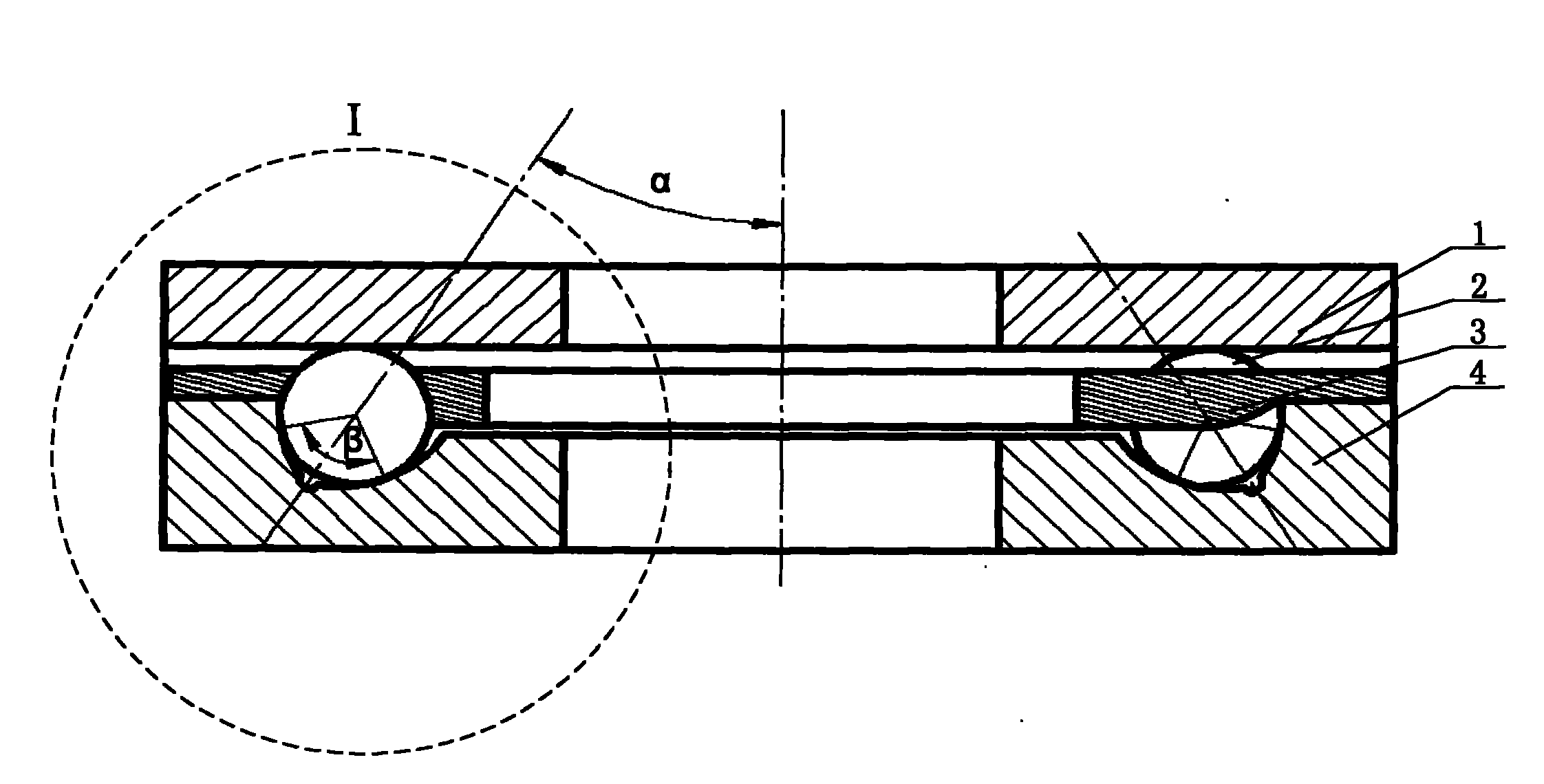
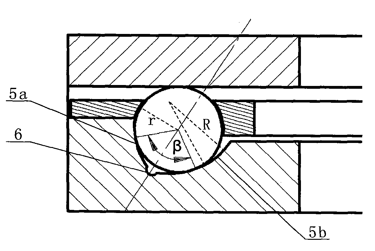
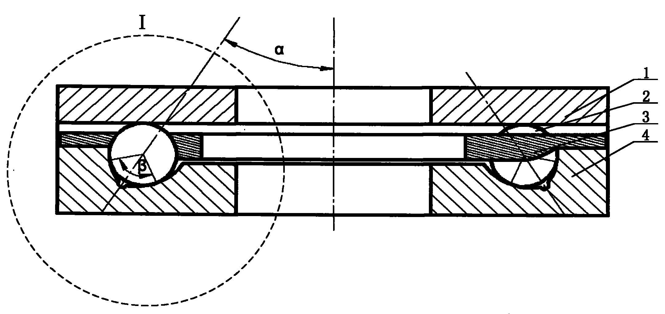
[0017] Such as figure 1 , 2 As shown in , the design method of the three-point contact thrust ball bearing of the present invention is based on improving the manufacturability of the bearing on the premise of ensuring the processing quality. The specific steps are as follows:

[0018] (1) Determine the outer dimensions of the bearing according to the allowable space of the bearing under specific working conditions, including the inner diameter d, outer diameter D and assembly height T of the bearing;

[0019] (2) Under the condition of ensuring the strength of the ring, the rated dynamic and static load of the bearing is used as the optimization objective function of the bearing design, and the steel ball diameter D of the bearing is determined w , the number of steel balls N and the pitch circle diameter D of the whole set of bearings pw ;

[0020] (3) A...


PUM


Abstract

The invention belongs to the technical field of thrust bearings and discloses a three-point contact thrust ball bearing and a design method. The three-point contact thrust ball bearing consists of a shaft washer, a housing washer, a steel ball and a retainer, wherein the housing washer is provided with an annular channel, the longitudinal section of the channel is an arc curve consisting of two segments of arcs, the steel ball and the annular channel on the housing washer are in two-point contact, the two arcs are symmetrical relative to the spinning rotary central line of the steel ball, an included angle alpha is formed between the central line and the central line of the bearing, and an included angle beta is formed between the connection lines of two contact points of the steel ball and the annular channel and the steel ball core; and the shaft washer is not provided with a channel, and the steel ball and the shaft washer is in one-point contact. The invention makes the steel ball, the shaft washer and the housing washer have three contact points, so the axial bearing capacity is increased, the bearing capacity is about 4 / 3 times of that of a two-point contact thrust ball bearing, and radial load can also be borne so as to prolong the service life of the bearing.

Description

technical field [0001] The invention belongs to the technical field of thrust bearings, and in particular relates to a three-point contact thrust ball bearing and a design method for a turntable mechanism. Background technique [0002] At present, the commonly used thrust ball bearing is composed of a shaft ring, a seat ring, steel balls and a cage. The steel ball and the cage are arranged between the shaft ring and the seat ring, and the steel ball rotates between the shaft ring and the seat ring. There are arc-shaped grooves on both the ring and the seat ring, and the radius of the arc is slightly larger than the radius of the steel ball. The thrust ball bearing of this structure only bears axial load, not radial load, and each steel ball and shaft There is only one contact point between the ring and the seat ring, and the axial load capacity of the bearing is limited; when the size of the thrust ball bearing is limited and it needs to bear a large axial load, the service ...

Claims


Application Information

Patent Timeline
IPC IPC(8): F16C19/16F16C33/58F16C33/66
Inventor 贺东锋刘乐民陈岩松
Owner HENAN SANWEI HEAVY IND
Learn More