Core cooling for electrical components

a technology of cooling system and electrical components, applied in the direction of transformer/inductance cooling, electrical apparatus construction details, transformer/react mounting/support/suspension, etc., can solve the problems of large component size, significant weight, and inefficient air-cooled inductors, so as to reduce heating, reduce electrical losses, and reduce internal temperature

Inactive Publication Date: 2006-03-02
ROCKWELL AUTOMATION TECH
View PDF13 Cites 51 Cited by
  • Summary
  • Abstract
  • Description
  • Claims
  • Application Information

AI Technical Summary

Benefits of technology

[0014] Cooling conduits are further arranged to run through the bobbin in a direction perpendicular to the coils to minimize possible negative effects on the electrical properties of the coils. These conduits can either terminate in the bobbin or continue through the bobbin to form a loop in more than one plane. The possibility of inducing a current in a single turn of a coil positioned in one plane is avoided. In addition, the conduit assembly for the cooling system can be shielded from the coil windings by dielectric end plates. The conduit assembly also minimizes the number of transverse portions in preference for portions that are in a direction perpendicular to the coils.
[0023] The invention will be a smaller device, which reduces shipping weight, required package structural strength, and material mass. All of these factors translate to decreased cost.

Problems solved by technology

Electrical resistance, for example, increases with heating and causes the equipment to be less efficient.
Traditional, air-cooled inductors are volumetrically inefficient.
These components are large in size and have significant weight.
Sealed boxes containing inductors of considerable size cannot be adequately air-cooled.

Method used


Image

  • Core cooling for electrical components
  • Core cooling for electrical components
  • Core cooling for electrical components

Examples


Embodiment Construction

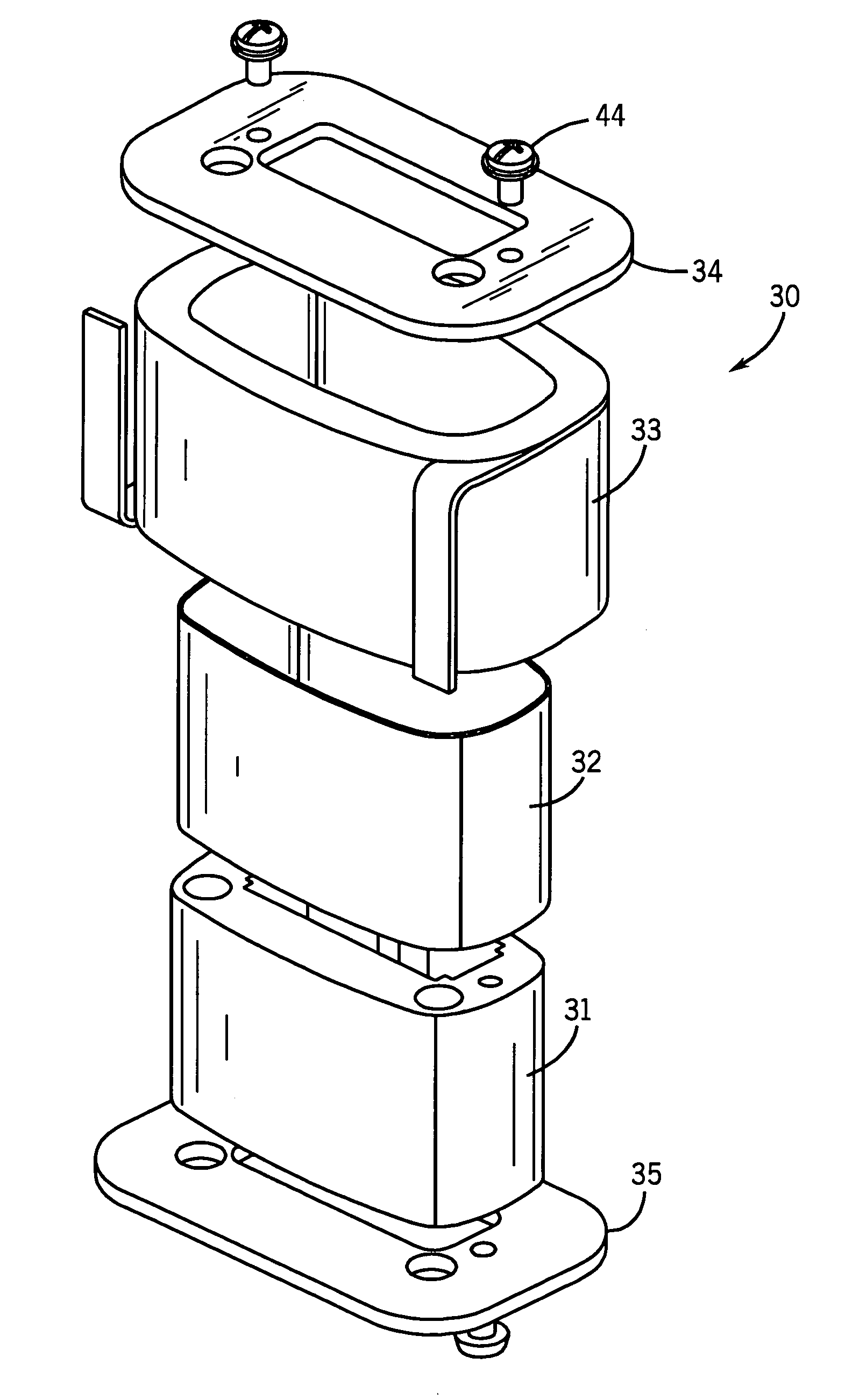
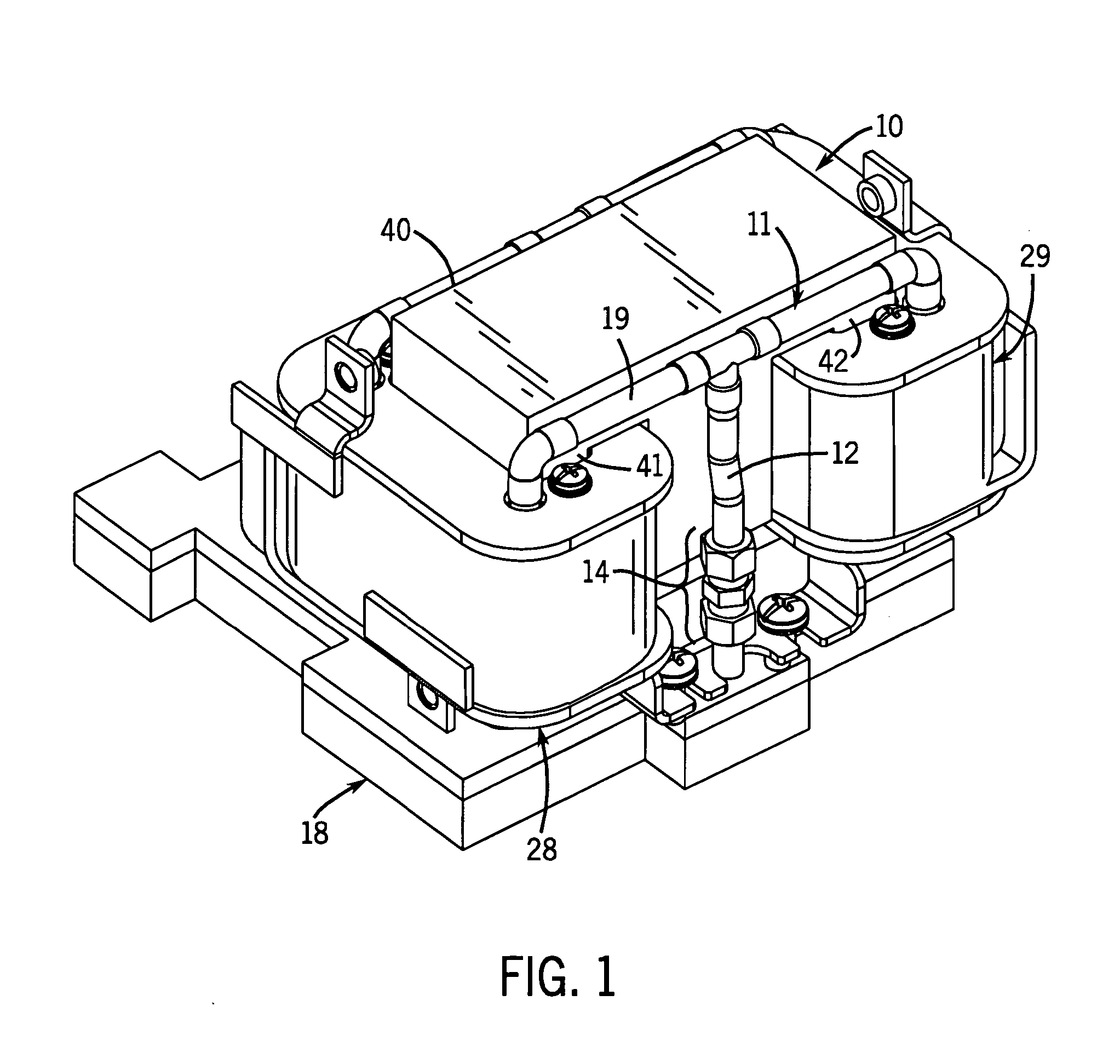
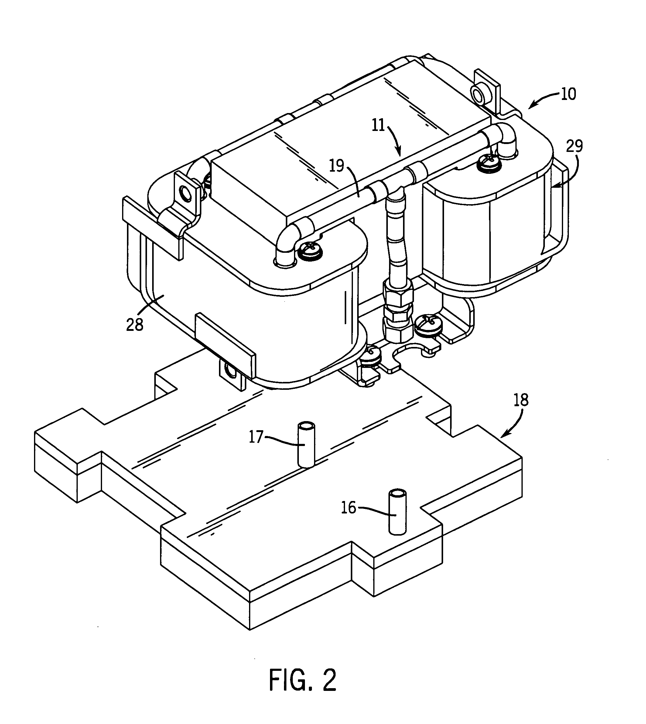
[0041]FIG. 1 illustrates an inductor assembly 10, which is a choke coil assembly, and which is constructed according to the present invention. The choke coil assembly 10 has a conduit assembly 11 for circulating a cooling fluid. As seen in FIGS. 1-3, the conduit assembly 11 is connected by vertical feed conduits 12 and 13 and couplings 14, 15 to conduit stubs 16, 17 in a cooling base plate 18. This base plate 18 has hollow portions for conveying the cooling fluid into and out of the conduit assembly 11 associated with the choke coil assembly 10. As seen in FIG. 1-3, the conduit assembly 11 forms a loop in three planes with two horizontal transverse runs 19, 20 across the top, four vertical runs 21, 22, 23 and 24 through the coil assemblies 28, 29 and two horizontal front-to-back runs 25 and 26 across the bottom which run at right angles to the top transverse runs 19 and 20.

[0042] The conduit assembly 11 is referred to as a “pass-through” type of conduit assembly because its conduit...


PUM

PropertyMeasurementUnit
conductiveaaaaaaaaaa
dielectricaaaaaaaaaa
symmetryaaaaaaaaaa

Abstract

A cooling system is provided for electrical components in which cooling assemblies (11, 45) are inserted in non-magnetic cores of the electrical components, and in which tubes provide both inflow and outflow of a cooling medium. The non-magnetic cores may be bobbins (30) for an inductor assembly or the core of a capacitor (40). The tubes may form a loop (11) in more than one plane to prevent inducing current in a single turn, or they may be split-flow closed-end tubes (45) inserted from one end of the electrical component. The bobbin cores (31) are also constructed with a non-conductive portion to prevent inducing a current in a single turn of a conductor.

Description

CROSS-REFERENCE TO RELATED APPLICATIONS [0001] Not Applicable STATEMENT REGARDING FEDERALLY SPONSORED RESEARCH [0002] Not Applicable TECHNICAL FIELD [0003] The field of the invention is cooling systems and methods for electrical control equipment and components. BACKGROUND ART [0004] Recent developments in hybrid vehicles and defense applications have increased the demand for cooling systems for electrical control equipment and components. [0005] The cooling of electrical components lowers their temperature of operation and increases their electrical efficiency and power output per unit size. Electrical resistance, for example, increases with heating and causes the equipment to be less efficient. The size and weight of electrical components can be reduced for a given power rating, provided that operating temperatures are kept within a certain range of ambient temperature by the use of cooling systems. [0006] It is typical to mount electrical controls in enclosures. Cooling of the el...

Claims


Application Information

Patent Timeline
Patent Type & Authority Applications(United States)
IPC IPC(8): H01F27/30
CPCH01F5/02H01F27/06H01F27/325H01F27/322H01F27/10
Inventor ROEBKE, TIMOTHY A.DAY, SCOTT D.KAISHIAN, STEVEN C.SIEBERT, WILLIAM K.KEHL, DENNIS L.
Owner ROCKWELL AUTOMATION TECH
Why Eureka
Try Eureka